PJON Doc
PJON v7.0
PJON™ (Padded Jittering Operative Network) is an Arduino compatible, multi-master, multi-media communications bus system. It proposes a Standard, it is designed as a framework and implements a totally software-emulated network protocol stack. It is a valid alternative to i2c, 1-Wire, Serial and other Arduino compatible protocols. Visit the Wiki, Documentation and Troubleshooting wiki pages to know more about the PJON Standard.
![]()
![]()


Features
- Configurable 2 level addressing (device and bus id) for scalable applications
- Multi-media support with the data link layer abstraction or Strategy framework
- Configurable strategies inclusion (for memory optimization)
- Configurable 1 or 2 bytes packet length (max 255 or 65535 bytes)
- Master-slave or multi-master dynamic addressing
- Configurable synchronous and/or asynchronous acknowledgement of correct packet sending
- Collision avoidance to enable multi-master capability
- Selectable CRC8 or CRC32 table-less cyclic redundancy check
- Packet manager to handle, track and if necessary retransmit a packet sending in background
- Optional ordered packet sending
- Error handling
PJON (Padded Jittering Operative Network) Protocol specification
Compliant tools
- saleae-pjon-protocol-analyzer by Andrew Grande
- PJON-python by Zbigniew Zasieczny
- ModuleInterface by Fred Larsen
PJON™ is a self-funded, no-profit open-source project created (in 2010) and mantained by Giovanni Blu Mitolo with the support ot the internet community if you want to see the PJON project growing with a faster pace, consider a donation at the following link: https://www.paypal.me/PJON
PJON™ and its brand are unregistered trademarks, property of Giovanni Blu Mitolo gioscarab@gmail.com
PJON Specifications
PJON Dynamic Addressing Spec v0.1
- PJDL (Padded Jittering Data Link) specification: PJDL v0.1 - PJDL v1.0 - PJDLR v1.0
- PJON (Padded Jittering Operative Network) Protocol specification: v0.1 - v0.2 - v0.3 - v1.0
- Acknowledge specification: v0.1
- Dynamic addressing specification: v0.1
/*
Milan, Italy - 02/10/2016
The PJON™ dynamic addressing specification is an invention and intellectual property
of Giovanni Blu Mitolo - Copyright 2010-2017 All rights reserved
Related work: https://github.com/gioblu/PJON/
Compliant implementation versions: PJON 5.2 and following
Inspired by the thesis of Thomas Snaidero:
"Modular components for eye tracking, in the interest of helping persons with severely impaired motor skills."
Master Thesis, IT University of Copenhagen, Denmark, September 2016
*/
###PJON™ dynamic addressing specification v0.1 This draft defines the dynamic addressing procedure used by a device in multi-master configuration or the one imposed and regulated by the master in a master-slave configuration.
###Master-slave dynamic addressing
  SLAVES
   _________     _________     _________     _________
  | ID    1 |   | ID    2 |   | ID    3 |   | ID    4 |
  | RID 101 |   | RID  41 |   | RID 945 |   | RID  22 |      __________
  |_________|   |_________|   |_________|   |_________|     |  MASTER  |
______|_____________|_____________|_____________|___________| ID   254 |
      ___|_____     ___|_____     ___|_____     ___|_____   |__________|
     | ID    5 |   | ID    6 |   | ID    7 |   | ID    8 |
     | RID 723 |   | RID  35 |   | RID 585 |   | RID  66 |
     |_________|   |_________|   |_________|   |_________|
####Master features
- The master id is
PJON_MASTER_ID(value 254) - Master has a caducous internal device archive
- Broadcasts
PJON_ID_LISTto getPJON_ID_REFRESHrequests from already approved devices - Handles
PJON_ID_REQUESTrequests from devices asking for device id assignment - Sends
PJON_ID_NEGATErequest to colliding or inconsistent devices - Handles
PJON_ID_NEGATErequests from slaves who are leaving the bus
####Slave features
- The slave initial device id is
PJON_NOT_ASSIGNED(value 255) - Slaves have a unique random generated 4 bytes id or rid
- Sends
PJON_ID_REFRESHrequest to master if required by masterPJON_ID_LISTbroadcast - Sends
PJON_ID_REQUESTto master if device id assignment is necessary - Regenerates rid and restarts the process if
PJON_ID_NEGATEis received from master - Sends
PJON_ID_NEGATEbefore shut down / leaving the bus - Fall back to multi-master procedure if no master is present
####Procedure
Slave sends an PJON_ID_REQUEST to get a new device id:
  ___________ __________ ________ ____________ _______ _______ _______ _______ _____     _____
 |           |  HEADER  |        |            |       |       |       |       |     |   |     |
>| MASTER_ID | 00010100 | LENGTH | ID_REQUEST | RID 1 | RID 2 | RID 3 | RID 4 | CRC |> <| ACK |
 |___________|__________|________|____________|_______|_______|_______|_______|_____|   |_____|
If master detects a device rid collision, sends a PJON_ID_NEGATE request to PJON_NOT_ASSIGNED device id to force
the collided device still not approved to regenerate a device rid:
  ______________ __________ ________ ___________ _______ _______ _______ _______ _____     _____
 |              |  HEADER  |        |           |       |       |       |       |     |   |     |
>| NOT_ASSIGNED | 00010100 | LENGTH | ID_NEGATE | RID 1 | RID 2 | RID 3 | RID 4 | CRC |> <| ACK |
 |______________|__________|________|___________|_______|_______|_______|_______|_____|   |_____|
Master broadcasts response containing the new id reserved for the device rid who requested:
  ___________ __________ ________ ____________ _______ _______ _______ _______ ____ _____
 |           |  HEADER  |        |            |       |       |       |       |    |     |
>| BROADCAST | 00010000 | LENGTH | ID_REQUEST | RID 1 | RID 2 | RID 3 | RID 4 | ID | CRC |>
 |___________|__________|________|____________|_______|_______|_______|_______|____|_____|
Slave device id acquisition confirmation:
  ___________ __________ ________ ____________ _______ _______ _______ _______ ____ _____     _____
 |           |  HEADER  |        |            |       |       |       |       |    |     |   |     |
>| MASTER_ID | 00010100 | LENGTH | ID_CONFIRM | RID 1 | RID 2 | RID 3 | RID 4 | ID | CRC |> <| ACK |
 |___________|__________|________|____________|_______|_______|_______|_______|____|_____|   |_____|
If master detects reference inconsistencies at this stage, sends a PJON_ID_NEGATE request to the slave id
to force the device requesting ID_CONFIRM to regenerate a rid and try again:
  ____ __________ ________ ___________ _______ _______ _______ _______ _____     _____
 |    |  HEADER  |        |           |       |       |       |       |     |   |     |
>| ID | 00010100 | LENGTH | ID_NEGATE | RID 1 | RID 2 | RID 3 | RID 4 | CRC |> <| ACK |
 |____|__________|________|___________|_______|_______|_______|_______|_____|   |_____|
If master experience temporary disconnection / malfunction on startup sends a PJON_ID_LIST broadcast request.
Slaves will receive the broadcast and dispatch an PJON_ID_REFRESH request for the master:
Master broadcast PJON_ID_LIST request:
  ___________ __________ ________ _________ _____
 |           |  HEADER  |        |         |     |
>| BROADCAST | 00010000 | LENGTH | ID_LIST | CRC |>
 |___________|__________|________|_________|_____|
Slave device PJON_ID_REFRESH request:
  ___________ __________ ________ ____________ _______ _______ _______ _______ ____ _____     _____
 |           |  HEADER  |        |            |       |       |       |       |    |     |   |     |
>| MASTER_ID | 00010100 | LENGTH | ID_REFRESH | RID 1 | RID 2 | RID 3 | RID 4 | ID | CRC |> <| ACK |
 |___________|__________|________|____________|_______|_______|_______|_______|____|_____|   |_____|
If the id requested by the slave is free in the reference, id is approved by the master and the exchange ends.
If the id is found already in use, the master sends an PJON_ID_NEGATE request forcing the slave to
acquire a new id through an PJON_ID_REQUEST:
Master sends PJON_ID_NEGATE request to the slave:
  _______ __________ ________ ___________ _______ _______ _______ _______ _____     _____
 | SLAVE |  HEADER  |        |           |       |       |       |       |     |   |     |
>|  ID   | 00010100 | LENGTH | ID_NEGATE | RID 1 | RID 2 | RID 3 | RID 4 | CRC |> <| ACK |
 |_______|__________|________|___________|_______|_______|_______|_______|_____|   |_____|
If slave wants to leave the bus must send a PJON_ID_NEGATE request to the master:
  ___________ __________ ________ ___________ _______ _______ _______ _______ ____ _____     _____
 |           |  HEADER  |        |           |       |       |       |       |    |     |   |     |
>| MASTER_ID | 00010100 | LENGTH | ID_NEGATE | RID 1 | RID 2 | RID 3 | RID 4 | ID | CRC |> <| ACK |
 |___________|__________|________|___________|_______|_______|_______|_______|____|_____|   |_____|
###Multi-master dynamic addressing
    _______     _______     _______     _______     _______
   |       |   |       |   |       |   |       |   |       |
   | ID 0  |   | ID 1  |   | ID 2  |   | ID 3  |   | ID 4  |
   |_______|   |_______|   |_______|   |_______|   |_______|
 ______|___________|___________|___________|___________|______
          ___|___     ___|___     ___|___     ___|___
         |       |   |       |   |       |   |       |
         | ID 5  |   | ID 6  |   | ID 7  |   | ID 8  |
         |_______|   |_______|   |_______|   |_______|
####Procedure In a multi-master scenario, the device actively looks for a free device id and make no use of its rid for this procedure:
- The device extracts a random device id and tries to contact that device
- If an answer is received, it adds one to the id and tries again
- If any answer is obtained from a device id, that is reserved
- The device receives for a random time to be able to answer to other devices interested in that device id
- The device tries to contact itself to probe collision, if no answer is received the device id is taken.
PJON Protocol Acknowledge Spec v0.1
- PJDL (Padded Jittering Data Link) specification: PJDL v0.1 - PJDL v1.0 - PJDLR v1.0
- PJON (Padded Jittering Operative Network) Protocol specification: v0.1 - v0.2 - v0.3 - v1.0
- Acknowledge specification: v0.1
- Dynamic addressing specification: v0.1
/*
Milan, Italy - 17/10/2016
The PJON™ protocol acknowledge specification is an invention and intellectual property
of Giovanni Blu Mitolo - Copyright 2010-2017 All rights reserved
Related work: https://github.com/gioblu/PJON/
Compliant implementation versions: PJON 6.0 and following
*/
###PJON™ protocol acknowledge specification v0.1 The PJON Standard supports both synchronous and asynchronous acknowledgement. This two mechanisms are defined to ensure that a packet transmission ended positively with no errors and can be used individually or together.
####Synchronous acknowledge
Channel analysis   Transmission                                     Response
    _____           ________________________________________           _____
   | C-A |         | ID |  HEADER  | LENGTH | CONTENT | CRC |         | ACK |
<--|-----|---< >---|----|----------|--------|---------|-----|--> <----|-----|
   |  0  |         | 12 | 00000100 |   5    |    64   |  72 |         |  6  |
   |_____|         |____|__________|________|_________|_____|         |_____|
The graph above contains a standard packet transmission with synchronous acknowledge request where the character @ or 64 is sent to device id 12 with 00000100 header. As defined by the PJON protocol layer specification v1.0 the third bit from right up in the header requests to transmitter a synchronous acknowledge response. How the synchronous acknowledgement procedure works depends on the medium and the strategy used, see PJDL v1.0 or PJDLR v1.0) specification.
####Asynchronous acknowledge
Channel analysis                     Transmission
   _____     _________________________________________________________________
  | C-A |   | ID |  HEADER  | LENGTH | SENDER ID | PACKET ID | CONTENT | CRC |
<-|-----|< >|----|----------|--------|-----------|-----------|---------|-----|>
  |  0  |   | 12 | 00001010 |   18   |    11     |    99     |   64    |     |
  |_____|   |____|__________|________|___________|___________|_________|_____|
The graph above contains a standard packet transmission with asynchronous acknowledge request where the character @ or 64 is sent to device id 12 with 0001110 header containing its packet id 99. As defined by the PJON protocol layer specification v1.0 the fourth bit from right up in the header requests to transmitter an asynchronous acknowledge response and the presence of the packet id. The second bit from right up signals the inclusion of the sender’s info necessary to send back an asynchronous acknowledge packet when received.
####PJON™ recursive acknowledgement pattern In a scenario where there is no direct communication between two devices, a synchronous acknowledgement can’t be obtained successfully, so an asynchronous acknowledgement packet has to be sent back from receiver to the packet’s transmitter to inform of the correct packet reception.
    BUS 0.0.0.1                      BUS 0.0.0.2

    ______             ______             ______
   |      |           |      |           |      |
   | ID 0 |___________|ROUTER|___________| ID 0 |
   |______|           |______|           |______|
A router in the center is connected with two different buses, bus 0.0.0.1 and 0.0.0.2, communication between device 0 of bus 0.0.0.1 with device 0 of bus 0.0.0.2 can be obtain only through the router.
Channel analysis                     Transmission                                            Response
 _____     _______________________________________________________________________________     _____
| C-A |   | ID |  HEADER  | LENGTH |   BUS ID   | BUS ID | ID | PACKET ID | CONTENT | CRC |   | ACK |
|-----|< >|----|----------|--------|------------|--------|----|-----------|---------|-----|> <|-----|
|  0  |   | 0  | 00001111 |   16   |    0002    |  0001  | 0  |    99     |   64    |     |   |  6  |
|_____|   |____|__________|________|____________|________|____|___________|_________|_____|   |_____|
                                   |  RX INFO   |   TX INFO   |
In the packet shown above device 0 of bus 0.0.0.1 sends @ (64) to device 0 of bus 0.0.0.2. Being the header 00001000 bit up (asynchronous acknowledgement request) the packet is formatted containing the 2 bytes integer packet id 99 (used by receiver to send back an asynchronous acknowledgement packet) immediately after the sender information. Being header’s 00000100 bit up (synchronous acknowledgement request) receiver will acknowledge synchronously with an PJON_ACK (6) in case of correct reception or PJON_NAK (21) in case of mistake. This precise case is used as an example to show both features used at the same time to obtain an efficient and secure way to transmit packets with correct transmission certainty.
BUS 0.0.0.1                                                                            BUS 0.0.0.2

1 Packet tx                         2 rx, sync ACK, packet tx         3 rx, sync ACK, async ACK tx
TX START--->0-00001111-16-0002-0001-0-99-@-CRC-><-ACK->0-00001111-16-0002-0001-0-99-@-CRC-><-ACK-|
 ______                                        ______                                    ______  |
|      |                                      |      |                                  |      | |
| ID 0 |______________________________________|ROUTER|__________________________________| ID 0 | |
|______|                                      |______|                                  |______| |
                                                                                                 |
TX END-------ACK-><-0-00001111-15-0001-0002-0-99-CRC-<-ACK-><-0-00001111-15-0001-0002-0-99-CRC-<-|
                5 rx, sync ACK                4 rx, sync ACK, packet tx

/* If packet length - its overhead is 4, it is an asynchronous acknowledgement packet
   containing only its packet id */
- Device
0sends the packet, the router has a route to device0of bus0.0.0.2so responds with a synchronous acknowledgement
  _____ __________ ________ _________ _________ ____ ___________ _________ _______     _____
 | ID  |  HEADER  | LENGTH | BUS ID  | BUS ID  | ID | PACKET ID | CONTENT |  CRC  |   | ACK |
>|  0  | 00001111 |   16   | 0.0.0.2 | 0.0.0.1 | 0  |    99     |   64    |       |> <|  6  |
 |_____|__________|________|_________|_________|____|___________|_________|_______|   |_____|
                           | RX iNFO |   TX INFO    |
- Device
0of bus0.0.0.1wait for an asynchronous acknowledgement of the packet sent. Router sends to device id0of bus0.0.0.2and receives a synchronous acknowledgement
  _____ __________ ________ _________ _________ ____ ___________ _________ _______     _____
 | ID  |  HEADER  | LENGTH | BUS ID  | BUS ID  | ID | PACKET ID | CONTENT |  CRC  |   | ACK |
>|  0  | 00001111 |   16   | 0.0.0.2 | 0.0.0.1 | 0  |    99     |   64    |       |> <|  6  |
 |_____|__________|________|_________|_________|____|___________|_________|_______|   |_____|
                           | RX iNFO |   TX INFO    |
- Device
0of bus0.0.0.2sends an asynchronous acknowledgement packet to device0of bus0.0.0.1. Router has a route to device0of bus0.0.0.1so responds with a synchronous acknowledgement and device0of bus0.0.0.2ends the transaction after receiving a synchronous acknowledgement by the router
  _____ __________ ________ _________ _________ ____ ___________ _______     _____
 | ID  |  HEADER  | LENGTH | BUS ID  | BUS ID  | ID | PACKET ID |  CRC  |   | ACK |
>|  0  | 00001111 |   15   | 0.0.0.1 | 0.0.0.2 | 0  |    99     |       |> <|  6  |
 |_____|__________|________|_________|_________|____|___________|_______|   |_____|
                           | RX iNFO |   TX INFO    |
- Device
0of bus0.0.0.2ends the transaction after receiving a synchronous acknowledgement by the router. Device0of bus0.0.0.1receives the asynchronous acknowledgement packet forwarded by the router and responds with a synchronous acknowledgement.
  _____ __________ ________ _________ _________ ____ ___________ _______     _____
 | ID  |  HEADER  | LENGTH | BUS ID  | BUS ID  | ID | PACKET ID |  CRC  |   | ACK |
>|  0  | 00001111 |   15   | 0.0.0.1 | 0.0.0.2 | 0  |    99     |       |> <|  6  |
 |_____|__________|________|_________|_________|____|___________|_______|   |_____|
                           | RX iNFO |   TX INFO    |
This documents doesn’t want to specify in any way the routing mechanism (still not officially specified), but uses routing as a necessary example to showcase clearly the power of the recursive acknowledgement pattern.
PJON Protocol Spec v0.1
- PJDL (Padded Jittering Data Link) specification: PJDL v0.1 - PJDL v1.0 - PJDLR v1.0
- PJON (Padded Jittering Operative Network) Protocol specification: v0.1 - v0.2 - v0.3 - v1.0
- Acknowledge specification: v0.1
- Dynamic addressing specification: v0.1
/*
Milan, Italy - 10/04/2010
The PJON™ protocol specification is an invention and intellectual property
of Giovanni Blu Mitolo - Copyright 2010-2017 All rights reserved
Related work: https://github.com/gioblu/PJON
Compliant implementation versions: PJON 1.0-3.0-beta
*/
###PJON™ Protocol specification v0.1 The first experimental specification of the PJON protocol has been drafted with the goal of offering a new open-source, multi-master communications bus system Standard. Its more common applications are in the field of internet of things and embedded systems. Extended tests proved its effectiveness on different media like electricity, radio frequency and light.
###Basic concepts
- Every device has an unique 1 byte ID (0-255)
- Every device transmits and receives on the same common medium
- Every device has an equal right to transmit and receive on the common medium
- Every device can be connected to n PJON network media (with n dedicated pins)
- Transmission occurs only if the communication medium is not in use
- Synchronization occurs every byte
- Devices communicate through packets
###Packet transmission The concept of packet enables to send a communication payload to every connected device with correct reception certainty. A packet contains the recipient id, the length of the packet, its content and the CRC. Here is an example of a packet sending to device id 12 containing the string “@”:
 ID 12       LENGTH 4    CONTENT 64  CRC 130
 __________  __________  __________  ____________
| Byte     || Byte     || Byte     || Byte       |
|     __   ||      _   ||  _       ||  _      _  |
|    |  |  ||     | |  || | |      || | |    | | |
|0000|11|0 ||00000|1|00||0|1|000000||0|1|0000|1|0|
|____|__|__||_____|_|__||_|_|______||_|_|____|_|_|
A standard packet transmission is a bidirectional communication between two devices that can be divided in 3 different phases: channel analysis, transmission and response.
  Channel analysis   Transmission                            Response
      _____           _____________________________           _____
     | C-A |         | ID | LENGTH | CONTENT | CRC |         | ACK |
  <--|-----|---------|----|--------|---------|-----|--> <----|-----|
     |  0  |         | 12 |   4    |   64    | 130 |         |  6  |
     |_____|         |____|________|_________|_____|         |_____|
In the first phase the bus is analyzed by transmitter reading 10 logical bits, if any logical high is detected, the channel is considered free and transmission phase starts in which the packet is entirely transmitted. Receiver calculates CRC and starts the response phase transmitting a single byte, PJON_ACK (dec 6) in case of correct reception or PJON_NAK (dec 21) if an error in the packet’s content is detected. If transmitter receives no answer or PJON_NAK the packet sending has to be scheduled with a delay of ATTEMPTS * ATTEMPTS with a maximum of 250 ATTEMPTS to obtain data transmission quadratic back-off.
###Bus A PJON Bus is made by a group of up to 255 devices transmitting and receiving on the same medium. Communication between devices occurs through packets and it is based on democracy: every device has the right to transmit on the common medium for up to (1000 / devices number) milliseconds / second.
    _______     _______     _______     _______    _______
   |       |   |       |   |       |   |       |   |       |
   | ID 0  |   | ID 1  |   | ID 2  |   | ID 3  |   | ID 4  |
   |_______|   |_______|   |_______|   |_______|   |_______|
 _____|___________|___________|___________|___________|_______
         ____|__     ____|__     ____|__     ____|__
        |       |   |       |   |       |   |       |
        | ID 5  |   | ID 6  |   | ID 7  |   | ID 8  |
        |_______|   |_______|   |_______|   |_______|
PJON Protocol Spec v0.2
- PJDL (Padded Jittering Data Link) specification: PJDL v0.1 - PJDL v1.0 - PJDLR v1.0
- PJON (Padded Jittering Operative Network) Protocol specification: v0.1 - v0.2 - v0.3 - v1.0
- Acknowledge specification: v0.1
- Dynamic addressing specification: v0.1
/*
Milan, Italy - 19/08/2015
The PJON™ protocol specification is an invention and intellectual property
of Giovanni Blu Mitolo - Copyright 2010-2017 All rights reserved
Related work: https://github.com/gioblu/PJON/
Compliant implementation versions: PJON 3.0-beta-3.0
New feature: Bus identification
*/
###PJON™ Protocol Specification v0.2 After more than 4 years of testing, a second, experimental draft of the PJON protocol specification has been released to continue to pursue the goal of providing a new and open-source, multi-master communications bus system Standard. The main changes contains the addition of a IPv4 like 4 byte bus id. This extends the network capabilities of the PJON protocol from 254 devices of the 0.1 version to 1.090.921.692.930 devices supported by the 0.2 version. It is created to provide the community with a new and easy way to communicate data and build a network of devices. Its more common applications are in the field of the internet of things and embedded systems. Extended tests proved its effectiveness on different media like electricity, radio and light.
###Basic concepts
- Every bus has a unique IPv4 like 4 bytes id
- Many buses can coexist on the same medium
- Every device has a unique 1 byte id
- Every device transmits and receives on the same common medium
- Every device has an equal right to transmit and receive on the common medium
- Every device can be connected to n PJON buses (with n dedicated pins)
- Transmission occurs only if the communication medium is not in use
- Synchronization occurs every byte
- Devices communicate through packets
The PJON protocol v0.2 handles internal bus connectivity and unique addressing for 254 devices, through bus communication with unique bus addressing for 4.294.967.295 buses, supporting up to 1.090.921.692.930 devices.
###Bus A PJON bus is made by a group of up to 254 devices transmitting and receiving on the same medium. Communication between devices occurs through packets and it is based on democracy: every device has the right to transmit on the common medium for up to (1000 / devices number) milliseconds / second.
    _______     _______     _______     _______     _______
   |       |   |       |   |       |   |       |   |       |
   | ID 0  |   | ID 1  |   | ID 2  |   | ID 3  |   | ID 4  |
   |_______|   |_______|   |_______|   |_______|   |_______|
 ______|___________|___________|___________|___________|______
          ___|___     ___|___     ___|___     ___|___
         |       |   |       |   |       |   |       |
         | ID 5  |   | ID 6  |   | ID 7  |   | ID 8  |
         |_______|   |_______|   |_______|   |_______|
###Packet transmission The concept of packet enables to send a communication payload to every connected device with correct reception certainty. A packet contains the recipient id, the length of the packet, its content and the CRC. In this example is shown a packet sending to device id 12 on a local bus containing the string “@”:
 ID 12       LENGTH 4    CONTENT 64  CRC 130
 __________  __________  __________  ____________
| Byte     || Byte     || Byte     || Byte       |
|     __   ||      _   ||  _       ||  _      _  |
|    |  |  ||     | |  || | |      || | |    | | |
|0000|11|00||00000|1|00||0|1|000000||0|1|0000|1|0|
|____|__|__||_____|_|__||_|_|______||_|_|____|_|_|
A standard local packet transmission is a bidirectional communication between two devices that can be divided in 3 different phases: channel analysis, transmission and response.
  Channel analysis   Transmission                            Response
      _____           _____________________________           _____
     | C-A |         | ID | LENGTH | CONTENT | CRC |         | ACK |
  <--|-----|---------|----|--------|---------|-----|--> <----|-----|
     |  0  |         | 12 |   4    |   64    | 130 |         |  6  |
     |_____|         |____|________|_________|_____|         |_____|
In the first phase the bus is analyzed by transmitter reading 10 logical bits, if any logical high is detected, the channel is considered free and transmission phase starts in which the packet is entirely transmitted. Receiver calculates CRC and starts the response phase transmitting a single byte, PJON_ACK (dec 6) in case of correct reception or PJON_NAK (dec 21) if an error in the packet’s content is detected. If transmitter receives no answer or PJON_NAK the packet sending has to be scheduled with a delay of ATTEMPTS * ATTEMPTS * ATTEMPTS with a maximum of 125 ATTEMPTS to obtain data transmission 3rd degree polynomial back-off.
In a shared medium it is necessary to define a bus id to isolate devices from outcoming communication of other buses nearby. Below is shown the same local transmission (with the obvious 0.0.0.0 or localhost bus id omitted) used as an example before, in a shared environment instead the packet’s content is prepended with the bus id:
Channel analysis  Transmission                                Response
    _____          _______________________________________     _____
   | C-A |        | ID | LENGTH | BUS ID  | CONTENT | CRC |   | ACK |
<--|-----|--------|----|--------|---------|---------|-----|> <|-----|
   |  0  |        | 12 |   8    | 0.0.0.1 |   64    | 130 |   |  6  |
   |_____|        |____|________|_________|_________|_____|   |_____|
Thanks to this rule it is not only possible to share a medium with neighbors, but also network with them and enhance connectivity for free.
###Bus network A PJON bus network is the result of n PJON buses sharing the same medium and or interconnection of PJON buses using routers. A router is a device connected to n PJON buses with n dedicated pins on n dedicated media, able to route a packet from a bus to anotherone.
   TWO BUSES CONNECTED THROUGH A ROUTER

       BUS ID 0.0.0.1                  BUS ID 0.0.0.2
    _______     _______              _______     _______
   |       |   |       |            |       |   |       |
   | ID 0  |   | ID 1  |            | ID 0  |   | ID 1  |
   |_______|   |_______|  ________  |_______|   |_______|
 ______|___________|_____| ROUTER |_____|___________|______
          ___|___        |  ID 3  |        ___|___
         |       |       |________|       |       |
         | ID 2  |                        | ID 2  |
         |_______|                        |_______|
In a shared medium it is necessary to define a bus id to isolate devices from outcoming communication of other buses nearby, enabling many to coexist on the same communication medium.
   TWO BUSES SHARING THE SAME MEDIUM

       BUS ID 0.0.0.1                  BUS ID 0.0.0.2
    _______     _______              _______     _______
   |       |   |       |            |       |   |       |
   | ID 0  |   | ID 1  |            | ID 0  |   | ID 1  |
   |_______|   |_______|            |_______|   |_______|
 ______|___________|___________________|___________|______
          ___|___                          ___|___
         |       |                        |       |
         | ID 2  |                        | ID 2  |
         |_______|                        |_______|
PJON Protocol Specification v0.3
- PJDL (Padded Jittering Data Link) specification: PJDL v0.1 - PJDL v1.0 - PJDLR v1.0
- PJON (Padded Jittering Operative Network) Protocol specification: v0.1 - v0.2 - v0.3 - v1.0
- Acknowledge specification: v0.1
- Dynamic addressing specification: v0.1
/*
Milan, Italy - 04/09/2016
The PJON™ protocol specification is an invention and intellectual property
of Giovanni Blu Mitolo - Copyright 2010-2017 All rights reserved
Related work: https://github.com/gioblu/PJON/
Compliant implementation versions: PJON 4.0-5.0
New feature: Header driven dynamical configuration proposed and implemented by Fred Larsen
*/
###PJON™ Protocol specification v0.3 A third draft of the PJON protocol has been released with the addition of a 1 byte header designed to contain the configuration for the packet’s communication procedure and its meta-data. In versions 0.1 and 0.2, the PJON communication procedure configuration was static and the header not present, for this reason two differently configured devices, could not establish nominal communication, without configuration pairing. It is now possible for the packet’s receiver to read the header, react as transmitter requested and parse the packet and its info correctly.
###Network protocol stack model The actual PJON network protocol stack model lacks segmentation and routing procedures, dedicated to higher level layers to be added during development.
 ___________________________________________
| PJON Protocol layer                       |
| Addressing, acknowledgement               |
| multiplexing, traffic control             |
|-------------------------------------------|
| STRATEGY                                  |
| Data link, transmission of data frames    |
|-------------------------------------------|
| Physical layer                            |
| Cable, transceivers ecc                   |
|___________________________________________|
###Basic concepts
- Every bus has a unique IPv4 like 4 bytes id
- Many buses can coexist on the same medium
- Every device has a unique 1 byte id
- Every device has an equal right to transmit and receive on the common medium
- Every device can be connected to n PJON buses
- Transmission occurs only if the communication medium is not in use
- Devices communicate through packets
- Packet transmission is regulated by a 1 byte header
The PJON protocol v0.3 handles internal bus connectivity and unique addressing for 254 devices, through bus communication with unique bus addressing for 4.294.967.295 buses, supporting up to 1.090.921.692.930 devices.
###Bus
A PJON bus is made by a group of up to 255 devices transmitting and receiving on the same medium. Communication between devices occurs through packets and it is based on democracy: every device has the right to transmit on the common medium for up to (1000 / devices number) milliseconds / second.
    _______     _______     _______     _______     _______
   |       |   |       |   |       |   |       |   |       |
   | ID 0  |   | ID 1  |   | ID 2  |   | ID 3  |   | ID 4  |
   |_______|   |_______|   |_______|   |_______|   |_______|
 ______|___________|___________|___________|___________|______
          ___|___     ___|___     ___|___     ___|___
         |       |   |       |   |       |   |       |
         | ID 5  |   | ID 6  |   | ID 7  |   | ID 8  |
         |_______|   |_______|   |_______|   |_______|
###Packet transmission A packet transmission is the exchange of a string to one of the devices connected to the bus with optional correct reception certainty. A packet contains the recipient id, its length, its header, its content and the CRC. In this example is shown a packet transmission in a local bus to device id 12 containing the string @ (decimal 64):
 ID 12       LENGTH 5     HEADER 1    CONTENT 64  CRC 72
 __________  ___________  __________  __________  ____________
| Byte     || Byte      || Byte     || Byte     || Byte       |
|     __   ||      _   _||      _   ||  _       ||  _    _    |
|    |  |  ||     | | | ||     | |  || | |      || | |  | |   |
|0000|11|00||00000|1|0|1||00000|1|00||0|1|000000||0|1|00|1|000|
|____|__|__||_____|_|_|_||_____|_|__||_|_|______||_|_|__|_|___|
A default local packet transmission is a bidirectional communication between two devices that can be divided in 3 different phases: channel analysis, transmission and response. The packet transmission procedure is regulated by its header.
Channel analysis   Transmission                                     Response
    _____           ________________________________________           _____
   | C-A |         | ID | LENGTH |  HEADER  | CONTENT | CRC |         | ACK |
<--|-----|---< >---|----|--------|----------|---------|-----|--> <----|-----|
   |  0  |         | 12 |   5    | 00000100 |    64   |  72 |         |  6  |
   |_____|         |____|________|__________|_________|_____|         |_____|
In the first phase the bus is analyzed by transmitter reading 10 logical bits, if any logical 1 is detected the channel is considered free, transmission phase starts in which the packet is entirely transmitted. Receiver calculates CRC and starts the response phase transmitting a single byte, PJON_ACK (decimal 6) in case of correct reception or PJON_NAK (decimal 21) if an error in the packet’s content is detected. If transmitter receives no answer or PJON_NAK the packet sending is scheduled with a delay of ATTEMPTS * ATTEMPTS * ATTEMPTS with a maximum of 125 ATTEMPTS to obtain data transmission 3rd degree polynomial back-off.
Below is shown the same local transmission used as an example before, formatted to be sent in a shared environment, where device id 12 of bus 0.0.0.1 sends @ (decimal 64) to device id 11 in bus id 0.0.0.1. The packet’s content is prepended with the bus id of the recipient, and optionally the sender’s bus and device id:
Channel analysis                     Transmission                              Response
 _____     _________________________________________________________________     _____
| C-A |   | ID | LENGTH | HEADER |   BUS ID   | BUS ID | ID | CONTENT | CRC |   | ACK |
|-----|< >|----|--------|--------|------------|--------|----|---------|-----|> <|-----|
|  0  |   | 12 |   14   |  111   |    0001    |  0001  | 11 |   64    |     |   |  6  |
|_____|   |____|________|________|____________|________|____|_________|_____|   |_____|
                                 |  RX INFO   |   TX INFO   |
###Header configuration The header bitmask let the packet’s receiver handle the exchange as transmitter requested.
 _______________________________________ _______________________________________
| 00000110 | Acknowledge requested     | Sender info included     | Local bus  | DEFAULT
| 00000100 | Acknowledge requested     | Sender info not included | Local bus  |
| 00000010 | Acknowledge not requested | Sender info included     | Local bus  |
| 00000000 | Acknowledge not requested | Sender info not included | Local bus  |
|----------|-------------------------- |--------------------------|------------|
| 00000111 | Acknowledge requested     | Sender info included     | Shared bus |
| 00000101 | Acknowledge requested     | Sender info not included | Shared bus |
| 00000011 | Acknowledge not requested | Sender info included     | Shared bus |
| 00000001 | Acknowledge not requested | Sender info not included | Shared bus |
|__________|___________________________|__________________________|____________|
As you can see for now, only the uppermost bit states are used for packet transmission exchange configuration, the unused bits may be used in future to extend or optimize the PJON Standard, so it is suggested not make use of them on application level.
###Bus network A PJON bus network is the result of n PJON buses sharing the same medium and or interconnection of PJON buses using routers. A router is a device connected to n PJON buses with n dedicated pins on n dedicated media, able to route a packet from a bus to anotherone. Thanks to this rule is not only possible to share a medium with neighbours, but also network with them and enhance connectivity for free.
   TWO BUSES CONNECTED THROUGH A ROUTER

       BUS ID 0.0.0.1                  BUS ID 0.0.0.2
    _______     _______              _______     _______
   |       |   |       |            |       |   |       |
   | ID 0  |   | ID 1  |            | ID 0  |   | ID 1  |
   |_______|   |_______|  ________  |_______|   |_______|
 ______|___________|_____| ROUTER |_____|___________|______
          ___|___        |  ID 3  |        ___|___
         |       |       |________|       |       |
         | ID 2  |                        | ID 2  |
         |_______|                        |_______|
In a shared medium it is necessary to define a bus id to isolate devices from outcoming communication of other buses nearby, enabling many to coexist on the same communication medium.
   TWO BUSES SHARING THE SAME MEDIUM

       BUS ID 0.0.0.1                  BUS ID 0.0.0.2
    _______     _______              _______     _______
   |       |   |       |            |       |   |       |
   | ID 0  |   | ID 1  |            | ID 0  |   | ID 1  |
   |_______|   |_______|            |_______|   |_______|
 ______|___________|___________________|___________|______
          ___|___                          ___|___
         |       |                        |       |
         | ID 2  |                        | ID 2  |
         |_______|                        |_______|
PJON Protocol Spec v1.0
- PJDL (Padded Jittering Data Link) specification: PJDL v0.1 - PJDL v1.0 - PJDLR v1.0
- PJON (Padded Jittering Operative Network) Protocol specification: v0.1 - v0.2 - v0.3 - v1.0
- Acknowledge specification: v0.1
- Dynamic addressing specification: v0.1
/*
Milan, Italy - 3/10/2016
The PJON™ protocol layer specification is an invention and intellectual property
of Giovanni Blu Mitolo - Copyright 2010-2016 All rights reserved
Related work: https://github.com/gioblu/PJON/
Compliant implementation versions: PJON 6.0 and following
New features:
- Header switched position with length to enable more than one byte length
- Optional extended header by Fred Larsen
- Header bits function definition
- Configurable 1 or 2 bytes length (max packet length 255/65535 bytes)
- Configurable CRC used (8/32 bit)
- Configurable auto-addressing
*/
###PJON™ Protocol specification v1.0 With this release, the PJON protocol layer has been vastly extended and generalized aiming to interoperability and to offer a real and complete alternative to the actual set of standards used for networking today. The strong plus of the approach used by the protocol mechanism is high efficiency and low overhead thanks to the configuration driven packet format, enabling easy constrain to application needs.
###Network protocol stack model In the graph below is shown the protocol stack model proposed. The differences between the OSI model and the PJON stack is the presence or absence of some features and how they are distributed in its layers. Those engineering choices are made to offer a scalable and low overhead stack of protocols able to be used as a set or individually. This stack has been engineered “bottom to top” and was originally applied as an alternative to 1-Wire or i2c, with this release features has been extended enabling many use cases where the OSI model is generally applied.
 -----------------------------------------------
| 7 Application layer                           |
| APIs, data sharing, remote access             |
|-----------------------------------------------|
| 6 Presentation layer                          |
| Encryption, encoding, data compression        |
|-----------------------------------------------|
| 5 Session layer                               |
| Session                                       |
|-----------------------------------------------|
| 4 Network layer                               |
| Routing, segmentation                         |
|-----------------------------------------------|
| 3 Protocol layer: PJON                        |
| Addressing, reliable packet transmission,     |
| multiplexing, traffic control,                |
| asynchronous acknowledgement                  |
|-----------------------------------------------|
| 2 Data link layer: PJDL/PJDLR                 |
| Data link, collision avoidance,               |
| synchronous acknowledgment                    |
|-----------------------------------------------|
| 1 Physical layer: Cables, transceivers ecc.   |
|_______________________________________________|
###Basic concepts
- Every bus has a unique IPv4 like 4 bytes id
- Many buses can coexist on the same medium
- Every device has an equal right to transmit and receive
- Every device can be connected to n PJON buses
- Every device has a unique 1 byte id
- Every device can obtain an id if available (see Dynamic addressing specification v0.1)
- Transmission occurs only if the communication medium is not in use
- Devices communicate through packets with a maximum length of 255 or 65535 bytes
- Packet transmission is regulated by a 1, 2 or 3 byte header
- Synchronous and or asynchronous acknowledgement can be requested (see Acknowledge specification v0.1)
The PJON protocol v1.0 handles internal bus connectivity and unique addressing for 254 devices, through bus communication with unique bus addressing for 4.294.967.295 buses and supports up to 1.090.921.692.930 devices. It regulates the exchange of packets with a configurable set of features driven by its header. Depending on the packet configuration a certain overhead is added to information varying from 3 up to 19 bytes.
###Bus
A PJON bus is made by a group of up to 254 devices transmitting and receiving on the same medium. Communication between devices occurs through packets and it is based on democracy: every device has the right to transmit on the common medium for up to (1000 / devices number) milliseconds / second.
    _______     _______     _______     _______     _______
   |       |   |       |   |       |   |       |   |       |
   | ID 0  |   | ID 1  |   | ID 2  |   | ID 3  |   | ID 4  |
   |_______|   |_______|   |_______|   |_______|   |_______|
 ______|___________|___________|___________|___________|______
          ___|___     ___|___     ___|___     ___|___
         |       |   |       |   |       |   |       |
         | ID 5  |   | ID 6  |   | ID 7  |   | ID 8  |
         |_______|   |_______|   |_______|   |_______|
###Bus network A PJON bus network is the result of n PJON buses sharing the same medium and or being interconnected to other PJON buses through routers. A router is a device connected to n PJON buses with n dedicated, potentially different, data link layers on n dedicated media, able to route a packet from a bus to another. Thanks to this rule is not only possible to share the same medium with neighbours, but also network with them and enhance connectivity.
   TWO BUSES CONNECTED THROUGH A ROUTER

       BUS ID 0.0.0.1                  BUS ID 0.0.0.2
    _______     _______              _______     _______
   |       |   |       |            |       |   |       |
   | ID 0  |   | ID 1  |            | ID 0  |   | ID 1  |
   |_______|   |_______|  ________  |_______|   |_______|
 ______|___________|_____| ROUTER |_____|___________|______
          ___|___        |  ID 3  |        ___|___
         |       |       |________|       |       |
         | ID 2  |                        | ID 2  |
         |_______|                        |_______|
In a shared medium it is defined a IPv4 like bus id to isolate devices from outcoming communication of other buses nearby, enabling many to coexist on the same communication medium.
   TWO BUSES SHARING THE SAME MEDIUM

       BUS ID 0.0.0.1                  BUS ID 0.0.0.2
    _______     _______              _______     _______
   |       |   |       |            |       |   |       |
   | ID 0  |   | ID 1  |            | ID 0  |   | ID 1  |
   |_______|   |_______|            |_______|   |_______|
 ______|___________|___________________|___________|______
          ___|___                          ___|___
         |       |                        |       |
         | ID 2  |                        | ID 2  |
         |_______|                        |_______|
###Packet transmission A packet transmission is an exchange of a string to one or many of the devices connected to the bus with optional correct reception certainty. The simplest form of packet is constructed by a recipient id, a header, the length, the content and its CRC. In this example is shown a packet transmission in a local bus to device id 12 containing the string @ (decimal 64):
 ID 12       HEADER 1    LENGTH 5     CONTENT 64  CRC 72
 __________  __________  ___________  __________  ____________
| Byte     || Byte     || Byte      || Byte     || Byte       |
|     __   ||      _   ||      _   _||  _       ||  _    _    |
|    |  |  ||     | |  ||     | | | || | |      || | |  | |   |
|0000|11|00||00000|1|00||00000|1|0|1||0|1|000000||0|1|00|1|000|
|____|__|__||_____|_|__||_____|_|_|_||_|_|______||_|_|__|_|___|
A default local packet transmission is a optionally bidirectional communication between two devices that can be divided in 3 different phases: channel analysis, transmission and optional response. The packet transmission procedure is regulated by its header:
HEADER BITMASK

     1          2          3         4         5         6         7         8
 __________ __________ _________ _________ _________ __________ _________ _________
|          |          |         |         |         |          |         |         | byte 1
| EXTENDED | EXTENDED |   CRC   | ADDRESS | ACKMODE |   ACK    | TX INFO |   MODE  |
|  HEADER  |  LENGTH  |         |         |         |          |         |         |
|__________|__________|_________|_________|_________|__________|_________|_________|
|          |          |         |         |         |          |         |         | byte 2
| EXTENDED | ROUTING  | SEGMENT | SESSION | PARITY  | ENCODING |  DATA   |  ENCRY  | OPTIONAL
|  HEADER  |          |  ATION  |         |         |          |  COMP.  |  PTION  |
|__________|__________|_________|_________|_________|__________|_________|_________|
|          |          |         |         |         |          |         |         | byte 3
|   N/A    |   N/A    |   N/A   |   N/A   |   N/A   |   N/A    |   N/A   |   N/A   | OPTIONAL
|          |          |         |         |         |          |         |         |
|__________|__________|_________|_________|_________|__________|_________|_________|
Header byte 1 bits roles:
- Extended header bit informs if the header is composed by 1 (value 0) or 2 bytes (value 1)
- Extended Length bit informs the receiver if the packet contains 1 (value 0) or 2 (value 1) bytes length
- CRC bit informs the receiver which CRC was used as check for the packet, CRC 8 (value 0) or CRC 32 (value 1)
- Address bit informs if the packet is part of an addressing procedure (value 1) or not (value 0)
- Acknowledge mode bit informs if the requested acknowledge is synchronous (value 0) or asynchronous (value 1)
- Acknowledge bit informs if acknowledge is requested (value 1) or not (value 0)
- Transmitter info bit informs if the sender info are included (value 1) or not (value 0)
- Mode bit informs if the packet is a shared mode (value 1) or if local mode formatted (value 0)
Header byte 2 bits roles:
- Extended header bit informs if the header is composed by 2 (value 0) or 3 bytes (value 1)
- Routing bit informs if routing meta-data is included (value 1) or not (value 0)
- Segmentation bit informs it part of a segmented transmission (value 1) or not (value 0)
- Session bit informs if session meta-data is included (value 1) or not (value 0)
- Parity bit informs if parity information for auto-correction is included (value 1) or not (value 0)
- Encoding bit informs if encoding meta-data is included (value 1) or not (value 0)
- Data compression bit informs if data compression meta-data is included (value 1) or not (value 0)
- Encryption bit informs if encryption meta-data is included (value 1) or not (value 0)
Channel analysis   Transmission                                     Response
    _____           ________________________________________           _____
   | C-A |         | ID |  HEADER  | LENGTH | CONTENT | CRC |         | ACK |
<--|-----|---< >---|----|----------|--------|---------|-----|--> <----|-----|
   |  0  |         | 12 | 00000100 |   5    |    64   |  72 |         |  6  |
   |_____|         |____|__________|________|_________|_____|         |_____|
In the first phase the bus is analyzed by transmitter reading 10 logical bits, if any logical 1 is detected the channel is considered free and transmission phase starts in which the packet is entirely transmitted. Receiver calculates CRC and starts the response phase transmitting a single byte, PJON_ACK (decimal 6) in case of correct reception or PJON_NAK (decimal 21) if an error in the packet’s content is detected. If transmitter receives no answer or PJON_NAK the packet sending is scheduled with a delay of ATTEMPTS * ATTEMPTS * ATTEMPTS * ATTEMPTS with a maximum of 42 ATTEMPTS to obtain data transmission 4rd degree polynomial back-off.
Below is shown the same local transmission used as an example before, formatted to be sent over a shared medium, where device id 12 of bus 0.0.0.1 sends @ (decimal 64) to device id 11 in bus id 0.0.0.1. The packet’s content is prepended with the bus id of the recipient, and optionally the sender’s bus and device id:
Channel analysis                     Transmission                                 Response
 _____     ___________________________________________________________________     _____
| C-A |   | ID |  HEADER  | LENGTH |   BUS ID   | BUS ID | ID | CONTENT | CRC |   | ACK |
|-----|< >|----|----------|--------|------------|--------|----|---------|-----|> <|-----|
|  0  |   | 12 | 00000111 |   14   |    0001    |  0001  | 11 |   64    |     |   |  6  |
|_____|   |____|__________|________|____________|________|____|_________|_____|   |_____|
                                   |  RX INFO   |   TX INFO   |
Configuring the header it is possible to leverage of the extended features of the protocol:
Channel analysis                     Transmission                                             Response
 _____     ________________________________________________________________________________     _____
| C-A |   | ID |  HEADER  | LENGTH 1 | LENGTH 2 |  BUS ID  | BUS ID | ID | CONTENT | CRC32 |   | ACK |
|-----|< >|----|----------|----------|----------|----------|--------|----|---------|-------|> <|-----|
|  0  |   | 12 | 01100111 |  byte 1  |  byte 2  |   0001   |  0001  | 11 |         |1|2|3|4|   |  6  |
|_____|   |____|__________|__________|__________|__________|________|____|_________|_|_|_|_|   |_____|
                                                | RX INFO  |   TX INFO   |
The graph above shows a packet transmission where the length is of 2 bytes supporting up to 65.535kB packet length. Receiver is able to parse the packet correctly reading the header, where B01000000 up signals a 2 bytes length format and B00100000 up signals CRC32 use.
Strategies
What is a Srategy?
PJON codebase uses strategies to physically communicate through the medium used, abstracting the data link layer from its procedure. We propose 6 strategies to communicate data through various media, take a look at the strategies video introduction for a brief showcase of their features. A Strategy is a class containing the back-off configuration and a set of methods able to send and receive messages:
bool begin(uint8_t additional_randomness = 0)
Returns true if the strategy is correctly initialized (receives a optional uint8_t used for randomness)
uint32_t back_off(uint8_t attempts)
Returns the suggested delay related to the attempts passed as parameter
bool can_start()
Returns true if the medium is free for use and false if the medium is in use by some other device
void handle_collision()
Handles a collision
uint8_t get_max_attempts()
Returns the maximum number of attempts in case of failed transmission
void send_string(uint8_t *string, uint16_t length)
Sends a string of a certain length through the medium
uint16_t receive_byte() { ... };
Receives a byte though the medium
void send_response(uint8_t response) { ... };
Send a response to the packet’s transmitter
uint16_t receive_response() { ... };
Receives a response from the packet’s receiver
You can define your own set of 5 methods to use PJON with your personal strategy on the media you prefer. If you need other custom configuration or functions, those can be defined in your personal Strategy class. Other communication protocols could be used inside those methods to transmit data.
// Simple Serial data link layer implementation example
void send_response(uint8_t response) {
  Serial.print(response);
};
How to define a new strategy
To define your new strategy you have only to create a new folder named for example YourStrategyName in strategies
directory and write the necessary file YourStrategyName.h:
class YourStrategyName {
  public:
    uint32_t back_off(uint8_t attempts) { ... };
    bool  begin(uint8_t additional_randomness) { ... };
    bool  can_start() { ... };
    uint8_t  get_max_attempts() { ... };
    uint16_t receive_byte() { ... };
    uint16_t receive_response() { ... };
    void     send_response(uint8_t response) { ... };
    void     send_string(uint8_t *string, uint16_t length) { ... };
};
Simply add your code in the functions declaration shown above and instantiate PJON using the strategy type you
have created: PJON<YourStrategyName> bus();.
PJON Supported Strategies
-
Software BitBang Spec
- PJDL (Padded Jittering Data Link) specification: PJDL v0.1 - PJDL v1.0 - PJDLR v1.0
- PJON (Padded Jittering Operative Network) Protocol specification: v0.1 - v0.2 - v0.3 - v1.0
- Acknowledge specification: v0.1
- Dynamic addressing specification: v0.1
/*
Milan, Italy - 10/04/2010
PJDL (Padded jittering data link) specification is an invention and intellectual property
of Giovanni Blu Mitolo - Copyright 2010-2017 All rights reserved

Related work: /strategies/SoftwareBitBang/
Compliant implementation versions: PJON 6.0 and following
*/
###PJDL (Padded Jittering Data Link) PJDL (Padded Jittering Data Link) has been specified to enable a new way to transmit data in simplex and half-duplex mode using cheap and low performance microcontrollers, totally software emulated, without the need of hardware interrupts for its working procedure. It is designed to support many devices sharing the same medium, to avoid collisions and operate in spite of interference. Extended tests proved its effectiveness on different media like electricity, radio frequency and light.
###Basic concepts
- Use a pattern of predefined initial padding bits to identify a potential byte transmission
- Use the falling edge from 1 to 0, present in padding bits, to achieve byte level synchronization
- Detect interference or absence of communication at byte level
- Enable channel analysis and collision avoidance
- Enable a collision free synchronous acknowledgement pattern
####Byte transmission Every byte is prepended with 2 synchronization padding bits and transmission occurs LSB-first. The first is a longer than standard logic 1 followed by a standard logic 0. The reception tecnique is based on finding a logic 1 as long as the first padding bit within a certain threshold, synchronizing to its falling edge and checking if it is followed by a logic 0. If this pattern is detected, reception starts, if not, interference, synchronization loss or simply absence of communication is detected at byte level.
 __________ ___________________________
| SyncPad  | Byte                      |
|______    |___       ___     _____    |
|  |   |   |   |     |   |   |     |   |
|  | 1 | 0 | 1 | 0 0 | 1 | 0 | 1 1 | 0 |
|_ |___|___|___|_____|___|___|_____|___|
   |
 SWBB_ACCEPTANCE (or minimum acceptable HIGH padding bit duration)
Padding bits are adding a certain overhead to information but are reducing the need of precise timing because synchronization is renewed every byte. All the first padding bit duration minus
SWBB_ACCEPTANCEis the synchronization window the receiver has for every incoming byte. If the length of the first padding bit is less thanSWBB_ACCEPTANCEthe received signal is considered interference.####Packet transmission Before a packet transmission, the medium is analyzed to detect ongoing communication and avoid collision. Thanks to the presence of padding bits, also a packet composed by 100 bytes, all with a decimal value of 0, can be transmitted safely without risk of third-party collision.
 ________________ _________________ ________________ ________________ __________________
|Sync | Byte     |Sync | Byte      |Sync | Byte     |Sync | Byte     |Sync | Byte       |
|___  |     __   |___  |      _   _|___  |      _   |___  |  _       |___  |  _    _    |
|   | |    |  |  |   | |     | | | |   | |     | |  |   | | | |      |   | | | |  | |   |
| 1 |0|0000|11|00| 1 |0|00000|1|0|1| 1 |0|00000|1|00| 1 |0|0|1|000000| 1 |0|0|1|00|1|000|
|___|_|____|__|__|___|_|_____|_|_|_|___|_|_____|_|__|___|_|_|_|______|___|_|_|_|__|_|___|
In a scenario where a stream of bytes is coming, low performance or clock inaccurate microcontrollers can be correctly synchronized back with transmitter every byte (thanks to padding bits) and easily detect interference or the end of transmission.
####Synchronous acknowledgement After packet reception, CRC is calculated and a single character is transmitted:
PJON_ACK(value 6) if the packet’s content is correct orPJON_NAK(value 21) if an error is detected.Transmission Response ________________________________________ _____ | ID | HEADER | LENGTH | CONTENT | CRC | CRC COMPUTATION | ACK | |----|----------|--------|---------|-----|-------> <-------|-----| | 12 | 00000100 | 5 | 64 | 72 | LATENCY | 6 | |____|__________|________|_________|_____| |_____|
Between a packet transmission and a synchronous acknowledgement transmission from the packet’s receiver there is a variable timeframe influenced in its duration by medium latency and CRC computation time. In order to avoid other devices to consider the medium free and start transmitting in the middle of a transmission and a response, the packet’s transmitter cyclically transmits a
BIT_WIDTH / 4HIGH bit and consequently attempts to receive a response. On the other side the receiver can synchronize its acknowledgement transmission after the last incoming HIGH bit and try more than once if necessary.Transmission Response ________________________________________ _ _ _ _ _ _ _ _____ | ID | HEADER | LENGTH | CONTENT | CRC | | | | | | | | | | | | | | | ACK | |----|----------|--------|---------|-----| | | | | | | | | | | | | | |-----| | 12 | 00000100 | 500 | | 72 | | | | | | | | | | | | | | | 6 | |____|__________|________|_________|_____|_| |_| |_| |_| |_| |_| |_| |_____|
The maximum time dedicated to potential acknowledgement reception and consequent channel jittering is defined by the use case constrains like maximum packet length and devices distance. Thanks to the presence of the jittering wave, many differently configured devices can coexist on the same medium with no risk of collision.
Padded Jittering Protocol Spec v0.1
- PJDL (Padded Jittering Data Link) specification: PJDL v0.1 - PJDL v1.0 - PJDLR v1.0
- PJON (Padded Jittering Operative Network) Protocol specification: v0.1 - v0.2 - v0.3 - v1.0
- Acknowledge specification: v0.1
- Dynamic addressing specification: v0.1
/*
Milan, Italy - 10/04/2010
The Padded jittering data link layer specification is an invention and intellectual property
of Giovanni Blu Mitolo - Copyright 2010-2017 All rights reserved

Related work: /strategies/SoftwareBitBang/
Compliant implementation versions: PJON 1.0-5.0
*/
###The Padded jittering data link layer The first experimental specification of the Padded jittering data link layer has been drafted to propose a new way to transmit data with cheap and low performance microcontrollers without the necessity of hardware interrupts for its working procedure. Thanks to the imposed requirement of non-concurrent and single-task execution, the Padded jittering data-link has a strong resilience also if the communication medium is affected by interference, high capacitance and resistance. Extended tests proved its effectiveness on different media like electricity, radio frequency and light.
###Basic concepts
- Use a pattern of predefined initial padding bits to identify a potential byte transmission
- Use the falling edge from 1 to 0, present in padding bits, to achieve byte level synchronization
- Detect interference or absence of communication at byte level
- Propose a collision free synchronous acknowledgement pattern
####Byte transmission Every byte is prepended with 2 synchronization padding bits and transmission occurs LSB-first. The first is a longer than standard logic 1 followed by a standard logic 0. The reception tecnique is based on finding a logic 1 as long as the first padding bit within a certain threshold, synchronizing to its falling edge and checking if it is followed by a logic 0. If this pattern is detected, reception starts, if not, interference, synchronization loss or simply absence of communication is detected at byte level.
 __________ ___________________________
| SyncPad  | Byte                      |
|______    |___       ___     _____    |
|  |   |   |   |     |   |   |     |   |
|  | 1 | 0 | 1 | 0 0 | 1 | 0 | 1 1 | 0 |
|_ |___|___|___|_____|___|___|_____|___|
   |
 ACCEPTANCE
Padding bits are adding a certain overhead to information but are reducing the need of precise time tuning because synchronization is renewed every byte. All the first padding bit duration minus
ACCEPTANCEis the synchronization window the receiver has for every incoming byte. If the length of the first padding bit is less thanACCEPTANCEthe received signal is considered interference.####String transmission
 ________________ _________________ ________________ ________________ __________________
|Sync | Byte     |Sync | Byte      |Sync | Byte     |Sync | Byte     |Sync | Byte       |
|___  |     __   |___  |      _   _|___  |      _   |___  |  _       |___  |  _    _    |
|   | |    |  |  |   | |     | | | |   | |     | |  |   | | | |      |   | | | |  | |   |
| 1 |0|0000|11|00| 1 |0|00000|1|0|1| 1 |0|00000|1|00| 1 |0|0|1|000000| 1 |0|0|1|00|1|000|
|___|_|____|__|__|___|_|_____|_|_|_|___|_|_____|_|__|___|_|_|_|______|___|_|_|_|__|_|___|
In a scenario where a stream of byte is coming, following this approach a low performance or clock inaccurate microcontroller can be correctly synchronized back with the transmitter every byte and easily detect an interference or the end of transmission.
####Synchronous acknowledgement After packet reception, the CRC is calculated and a single character is transmitted,
PJON_ACK(value 6) if the packet’s content is correct orPJON_NAK(value 21) if an error is detected.Transmission Response ________________________________________ _____ | ID | HEADER | LENGTH | CONTENT | CRC | CRC COMPUTATION | ACK | |----|----------|--------|---------|-----|-------> <-------|-----| | 12 | 00000100 | 5 | 64 | 72 | LATENCY | 6 | |____|__________|________|_________|_____| |_____|
Between a packet transmission and a synchronous acknowledgement transmission from the packet’s receiver there is a variable timeframe influenced in its duration by medium latency and CRC computation time. In order to avoid other devices to consider the medium free and start transmitting in the middle of a transmission and a response, the packet’s transmitter cyclically transmits a
BIT_WIDTH / 4HIGH bit and consequently attempts to receive a response. On the other side the receiver can synchronize its acknowledgement transmission after the last incoming HIGH bit and try more than once if necessary.Transmission Response ________________________________________ _ _ _ _ _ _ _ _____ | ID | HEADER | LENGTH | CONTENT | CRC | | | | | | | | | | | | | | | ACK | |----|----------|--------|---------|-----| | | | | | | | | | | | | | |-----| | 12 | 00000100 | 500 | | 72 | | | | | | | | | | | | | | | 6 | |____|__________|________|_________|_____|_| |_| |_| |_| |_| |_| |_| |_____|
The maximum time dedicated to potential acknowledgement reception and consequent channel jittering is defined by the use case constrains like maximum packet length and devices distance.
-
PJDLR Spec v1.0
- PJDL (Padded Jittering Data Link) specification: PJDL v0.1 - PJDL v1.0 - PJDLR v1.0
- PJON (Padded Jittering Operative Network) Protocol specification: v0.1 - v0.2 - v0.3 - v1.0
- Acknowledge specification: v0.1
- Dynamic addressing specification: v0.1
/*
Milan, Italy - 18/01/2017
PJDLR (Padded jittering data link) specification is an invention and intellectual property
of Giovanni Blu Mitolo - Copyright 2010-2017 All rights reserved

Related work: /strategies/SoftwareBitBang/
Compliant implementation versions: PJON 7.0 and following

New feature: Packet preamble by Fred Larsen
*/
###PJDLR (Padded jittering data link / R version) PJDLR (Padded jittering data link) has been specified to enable a new way to transmit data in simplex and half-duplex mode using cheap and low performance microcontrollers without the need of hardware interrupts for its working procedure. It is designed to support many devices sharing the same medium, to avoid collisions and operate in spite of interference. Extended tests proved its effectiveness on different media like electricity, radio frequency and light.
###Basic concepts
- Use a pattern of predefined initial padding bits to identify a potential byte transmission
- Use the falling edge from 1 to 0, present in padding bits, to achieve byte level synchronization
- Detect interference or absence of communication at byte level
- Enable channel analysis and collision avoidance
- Enable a collision free synchronous acknowledgement pattern
####Byte transmission Every byte is prepended with 2 synchronization padding bits and transmission occurs LSB-first. The first is a shorter than standard logic 1 followed by a standard logic 0. The reception tecnique is based on finding a logic 1 as long as the first padding bit within a certain threshold, synchronizing to its falling edge and checking if it is followed by a logic 0. If this pattern is detected, reception starts, if not, interference, synchronization loss or simply absence of communication is detected at byte level.
 _____ ___________________________
| Pad | Byte                      |
|_    |___       ___     _____    |
| |   |   |     |   |   |     |   |
|1| 0 | 1 | 0 0 | 1 | 0 | 1 1 | 0 |
|_|___|___|_____|___|___|_____|___|
Padding bits are adding a certain overhead to information but are reducing the need of precise time tuning because synchronization is renewed every byte. All the first padding bit duration is the synchronization window the receiver has for every incoming byte. If the duration of the first padding bit is longer than expected the received signal is considered interference.
####Packet transmission Before a packet transmission, the medium is analyzed to detect ongoing communication and avoid collision. Thanks to the presence of padding bits, also a packet composed by 100 bytes, all with a decimal value of 0, can be transmitted safely without experiencing third-party collision. After assessed that the medium is free to use, a packet preamble, composed of a long 1 and a long 0, is transmitted to let a potential receiver to adjust its gain to the transmitted signal magnitude. The duration of the preamble bits have to be adjusted to match hardware sensitivity, gain refresh time and signal to noise ratio.
 _________ ______________ _______________ ______________ ______________ ________________
|Preamble |Pad| Byte     |Pad| Byte      |Pad| Byte     |Pad| Byte     |Pad| Byte       |
|_____    |_  |     __   |_  |      _   _|_  |      _   |_  |  _       |_  |  _    _    |
|     |   | | |    |  |  | | |     | | | | | |     | |  | | | | |      | | | | |  | |   |
|  1  | 0 |1|0|0000|11|00|1|0|00000|1|0|1|1|0|00000|1|00|1|0|0|1|000000|1|0|0|1|00|1|000|
|_____|___|_|_|____|__|__|_|_|_____|_|_|_|_|_|_____|_|__|_|_|_|_|______|_|_|_|_|__|_|___|
In a scenario where a stream of bytes is coming, low performance or clock inaccurate microcontroller can be correctly synchronized back with transmitter every byte (thanks to padding bits) and easily detect an interference or the end of transmission.
####Synchronous acknowledgement After packet reception, CRC is calculated and a single character is transmitted:
PJON_ACK(value 6) if the packet’s content is correct orPJON_NAK(value 21) if an error is detected.Transmission Response ________ ________________________________________ ________ _____ |PREAMBLE| ID | HEADER | LENGTH | CONTENT | CRC | CRC COMPUTATION |PREAMBLE| ACK | |____ | | | | | |-------> <-------|____ | | | | | 12 | 00000100 | 5 | 64 | 72 | LATENCY | | | 6 | |____|___|____|__________|________|_________|_____| |____|___|_____|
Padded Jittering Protocol Spec v0.1
- PJDL (Padded Jittering Data Link) specification: PJDL v0.1 - PJDL v1.0 - PJDLR v1.0
- PJON (Padded Jittering Operative Network) Protocol specification: v0.1 - v0.2 - v0.3 - v1.0
- Acknowledge specification: v0.1
- Dynamic addressing specification: v0.1
/*
Milan, Italy - 10/04/2010
The Padded jittering data link layer specification is an invention and intellectual property
of Giovanni Blu Mitolo - Copyright 2010-2016 All rights reserved

Related work: /strategies/SoftwareBitBang/
Compliant implementation versions: PJON 1.0-5.0
*/
###The Padded jittering data link layer The first experimental specification of the Padded jittering data link layer has been drafted to propose a new way to transmit data with cheap and low performance microcontrollers without the necessity of hardware interrupts for its working procedure. Extended tests proved its effectiveness on different media like electricity, radio frequency and light.
###Basic concepts
- Use a pattern of predefined initial padding bits to identify a byte transmission
- Use the falling edge from 1 to 0, present in padding bits, to achieve byte level synchronization
- Detect interference or absence of communication at byte level
####Byte transmission Every byte is prepended with 2 synchronization padding bits and transmission occurs LSB-first. The first is a longer than standard logic 1 followed by a standard logic 0. The reception tecnique is based on finding a logic 1 as long as the first padding bit within a certain threshold, synchronizing to its falling edge and checking if it is followed by a logic 0. If this pattern is detected, reception starts, if not, interference, synchronization loss or simply absence of communication is detected at byte level.
 __________ ___________________________
| SyncPad  | Byte                      |
|______    |___       ___     _____    |
|  |   |   |   |     |   |   |     |   |
|  | 1 | 0 | 1 | 0 0 | 1 | 0 | 1 1 | 0 |
|_ |___|___|___|_____|___|___|_____|___|
   |
 ACCEPTANCE
Padding bits are adding a certain overhead to information but are reducing the need of precise time tuning because synchronization is renewed every byte. All the first padding bit duration minus
ACCEPTANCEis the synchronization window the receiver has for every incoming byte. If the length of the first padding bit is less thanACCEPTANCEthe received signal is considered interference.________________ _________________ ________________ ________________ __________________ |Sync | Byte |Sync | Byte |Sync | Byte |Sync | Byte |Sync | Byte | |___ | __ |___ | _ _|___ | _ |___ | _ |___ | _ _ | | | | | | | | | | | | | | | | | | | | | | | | | | | | | | | 1 |0|0000|11|00| 1 |0|00000|1|0|1| 1 |0|00000|1|00| 1 |0|0|1|000000| 1 |0|0|1|00|1|000| |___|_|____|__|__|___|_|_____|_|_|_|___|_|_____|_|__|___|_|_|_|______|___|_|_|_|__|_|___|
In a scenario where a stream of byte is coming, following this strategy a low performance or clock inaccurate microcontroller can be correctly synchronized back with the transmitter every byte and easily detect an interference or the end of transmission.
Hardware/Software Serial port
Medium: Hardware/Software Serial port | Pins used: 1 or 2
With ThroughSerial data link layer strategy, PJON can run through a software emulated or hardware Serial port. Thanks to this choice it is possible to leverage of virtually all the arduino compatible serial transceivers, like RS485, radio or infrared modules, still having PJON unchanged on top. Take a look at the video introduction for a brief showcase of its features.
Why PJON over Serial?
Serial communication is an hardware integrated or software emulated data communication that can reach very fast communication speed but it includes only the data link layer; adding PJON on top of the Serial data link layer it is possible to leverage of the PJON protocol layer features like acknowledge, addressing, multiplexing, packet handling, 8-bit CRC and traffic control.
How to use ThroughSerial
Pass the ThroughSerial type as PJON template parameter to instantiate a PJON object ready to communicate through this Strategy.
PJON<ThroughSerial> bus; // 2 pin over-sampled data link layer
Call the begin method on the Serial or SoftwareSerial object you want to use for PJON communication and pass it to the set_serial method:
  /* Set 100 milliseconds is the maximum timeframe between every receive call
     in any of the connected devices. If this timeframe is in average exceeded
     by some of the connected devices, communication reliability could drop
     or be disrupted. (before PJON.h inclusion) */
  #define TS_MAX_BYTE_TIME          1000000

  /* Set 0.5 milliseconds as the minimum timeframe of free port before transmitting
     (before PJON.h inclusion) */
  #define TS_FREE_TIME_BEFORE_START     500

  /* This timing configuration is ok for a master-slave setup, but could lead to
     collisions if used in a multi-master setup.

  If using ThroughSerial in a multi-master setup with synchronous acknowledgment
  NEVER set TS_FREE_TIME_BEFORE_START < TS_MAX_BYTE_TIME or a device could start
  transmitting while a couple is still exchanging an acknowledge */
  #define TS_MAX_BYTE_TIME           100000

  #define TS_FREE_TIME_BEFORE_START  110000

  /* Above is shown multi-master compatible setup able to receive a synchronous
     acknowledgment with a maximum delay 100 milliseconds. Channel analysis before
     transmission is set to 110 milliseconds to avoid collisions.

     Which is the correct value for your setup depends on the maximum average time
     interval between every receive call in your system. TS_MAX_BYTE_TIME
     should be around the same duration. So in a sketch where there is only a
     delay(10) between every receive call at least 10000 should be the correct
     value for TS_MAX_BYTE_TIME.

     If your tasks timing are long and a satisfactory setup can't be reached
     consider to drop the use of the synchronous acknowledge and start using the
     asynchronous acknowledgment instead. */

  /* Set the back-off exponential degree */
  #define TS_BACK_OFF_DEGREE              4

  /* Set the maximum sending attempts */
  #define TS_MAX_ATTEMPTS                20

  /* The values set above are the default producing a 3.2 seconds
     back-off timeout with 20 attempts. Higher TS_MAX_ATTEMPTS to higher
     the back-off timeout, higher TS_BACK_OFF_DEGREE to higher the interval
     between every attempt. */

  #include <PJON.h>

  PJON<SoftwareBitBang> bus;

  void setup() {
    Serial.begin(9600);
    bus.strategy.set_serial(&Serial);
  }
For a simple use with RS485 serial modules a transmission enable pin setter has been added:
bus.strategy.set_enable_RS485_pin(11);
All the other necessary information is present in the general Documentation.
Known issues
- Being PJON not an interrupt driven, its communication can be affected and potentially disrupted by long delays added in the user’s sketch. Try to reduce as possible the interval between every
receivecall. A delay between every receive call higher than 100 millisseconds can disurpt the synchronous acknowledment transmission phase, higherTS_MAX_BYTE_TIMEinThroughSerial.hif necessary.
Software BitBang
Medium: Wire | Pins used: 1 / 2
SoftwareBitBang is the default data link layer strategy used by PJON. This implementation is based on micros() and delayMicroseconds(). It is totally software emulated and makes no use of dedicated timers or interrupt driven strategies to handle communication. It is designed to have a small memory footprint and to be extremely resilient to interference and timing inaccuracies. Thanks to the use of a dedicated PJON_IO library, can be achieved fast and reliable cross-architecture communication through one or two pins. It complies with PJDL v1.0 Data link layer specification. Take a look at the video introduction for a brief showcase of its features.
####Compatibility
- ATmega88/168/328 16Mhz (Diecimila, Duemilanove, Uno, Nano, Mini, Lillypad)
- ATmega2560 16Mhz (Arduino Mega)
- ATmega16u4/32u4 16Mhz (Arduino Leonardo)
- ATtiny45/85 8Mhz, see https://github.com/gioblu/PJON/wiki/ATtiny-interfacing
- SAMD (Arduino Zero)
- ESP8266 v.1-7 80Mhz “AI-THINKER AT” firmware, see https://github.com/esp8266/Arduino
- ESP8266 NodeMCU v0.9-1.0 80Mhz, see https://github.com/esp8266/Arduino
- MK20DX256 96Mhz (Teensy 3.1)
Performance
PJON works in 3 different communication modes, STANDARD, FAST and OVERDRIVE:
STANDARDruns at 16944Bd or 2.12kB/s cross-architecture, promiscuous clock/architecture compatible.FASTruns at 25157Bd or 3.15kB/s cross-architecture, promiscuous clock/architecture compatible.OVERDRIVEruns a specific architecture at its maximum limits (non cross-architecture compatible). Every architecture has its own limits, Arduino Duemilanove for example runs at 33898Bd or 4.23kB/s, Arduino Zero can reach 48000Bd or 6.00kB/s.
When including and using SoftwareBitBang, as data link layer of a PJON bus, you have the complete access to the microntroller ready to be used, as usual, untouched. This happens because SoftwareBitBang is completely software emulated strategy with a non blocking implementation, transforming a painfull walk to the hill in a nice flight.
Single wire simplicity let you to experiment quickly and with creativity. The first suggested test, at the tester’s risk, is to let two arduino boards communicate through a living body touching with the left hand the digital port of the first board (5v 40ma, harmless) and with the right the port of the other one. It is stunning to see highly accurate digital communication running inside a living biological body. This opens the mind to possible creative solutions.
How to use SoftwareBitBang
Pass the SoftwareBitBang type as PJON template parameter to instantiate a PJON object ready to communicate in this Strategy. All the other necessary information is present in the general Documentation.
  /* The default SoftwareBitBang mode is _SWBB_STANDARD
     (Transfer speed: 16.944kBb or 2.12kB/s) */

  /* Set SoftwareBitBang mode to _SWBB_FAST before PJON.h inclusion
     (Transfer speed: 25.157kBd or 3.15kB/s) */
  #define SWBB_MODE 2

  /* Set SoftwareBitBang mode to _SWBB_OVERDRIVE before PJON.h inclusion
     (Architecture / Toolchain dependant) */
  #define SWBB_MODE 3

  /* Acknowledge latency maximum duration (1000 microseconds default).
     Could be necessary to higher SWBB_LATENCY if sending long packets because
     of the CRC computation time needed by receiver before transmitting its acknowledge  */
  #define SWBB_LATENCY 1000

  /* Set the back-off exponential degree */
  #define SWBB_BACK_OFF_DEGREE 4

  /* Set the maximum sending attempts */
  #define SWBB_MAX_ATTEMPTS 20

  /* The values set above are the default producing a 3.2 seconds
     back-off timeout with 20 attempts. Higher SWBB_MAX_ATTEMPTS to higher
     the back-off timeout, higher SWBB_BACK_OFF_DEGREE to higher the interval
     between every attempt. */

  #include <PJON.h>

  PJON<SoftwareBitBang> bus;

  void setup() {
    bus.strategy.set_pin(12);       // Set the pin 12 as the communication pin
                                    // or
    bus.strategy.set_pins(11, 12);  // Set pin 11 as input pin and pin 12 as output pin
  }
After the PJON object is defined with its strategy it is possible to set the communication pin accessing to the strategy present in the PJON instance.
Why not interrupts?
The use of libraries is really extensive in the Arduino environment and often the end user is not able to go over collisions. Very often a library is using hardware resources of the microcontroller as timers or interrupts, colliding or interrupting other libraries. This happens because in general Arduino boards have limited hardware resources. To have a universal and reliable communication medium in this sort of environment, software emulated bit-banging, is a good, stable and reliable solution that leads to “more predictable” results than interrupt driven systems coexisting on small microcontrollers without the original developer and the end user knowing about it.
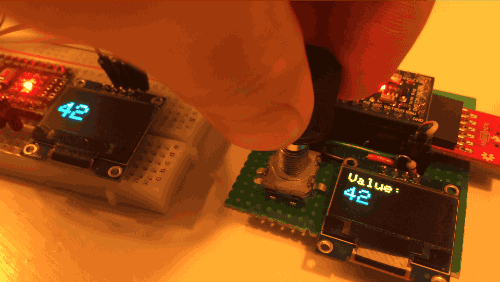
PJON application example made by the user Michael Teeuw
Known issues
- A pull down resistor in the order of mega ohms could be necessary on the bus to reduce interference, see deal with interference. In late november 2016 a bug has been discovered, it was on many devices creating a slight inconsistency in the channel state during transitions, most of the times disappearing with the use of a pull-down resistor (120b2c), with this bugfix the channel is much more reliable and in most cases there is no more need of a pull-down resistor to have nominal communication speed.
- Consider that this is not an interrupt driven system and so all the time passed
in delay or executing something a certain amount of packets could be potentially
lost not received, the packet manager of PJON will do its job scheduling the packet
to be sent again in future until is received or
PJON_MAX_ATTEMPTSsending attempts is reached, but a certain amount of bandwidth can be wasted. Structure intelligently your loop cycle to avoid huge blind timeframes. SoftwareBitBangstrategy can have compatibility issues with codebases that are using interrupts in their procedure, like for example the Servo library. Reliability or bandwidth loss can be experienced because of the cyclical interruptions made by third party interrupt driven software to the PJON code.
Oversampling
Media: Radio, Wire | Pins used: 1 / 2
Oversampling strategy was initially developed in the PJON_ASK repository, and it was integrated in the PJON repository from version 3.0 beta, as a data link layer strategy. Bits are over-sampled to have high resilience in high interference scenarios, like using an ASK/FSK cheap radio transceivers in an urban environment. It is tested effectively with many versions of the ASK/FSK 315/433Mhz modules available on the market, but it works nominally also through wires and the human body. It complies with PJDLR v1.0 Data link layer specification. Take a look at the video introduction for a brief showcase of its features.
Compatibility
- ATmega88/168/328 16Mhz (Diecimila, Duemilanove, Uno, Nano, Mini, Lillypad)
- ATmega2560 16Mhz (Arduino Mega)
- ATmega16u4/32u4 16Mhz (Arduino Leonardo)
Performance
- Transfer speed: 202 B/s or 1620 Baud
- Data throughput: 150 B/s
- Range: 250 meters in urban environment / 5km with line of sight and ideal atmospheric conditions
How to use OverSampling
Pass the OverSampling type as PJON template parameter to instantiate a PJON object ready to communicate in this Strategy. All the other necessary information is present in the general Documentation.
  /* Maximum latency can be set defining OS_LATENCY before PJON.h inclusion
     (Default 4 milliseconds) */
  #define OS_LATENCY 4000

  /* Set the back-off exponential degree */
  #define OS_BACK_OFF_DEGREE 4

  /* Set the maximum sending attempts */
  #define OS_MAX_ATTEMPTS 20

  /* The values set above are the default producing a 3.2 seconds
     back-off timeout with 20 attempts. Higher OS_MAX_ATTEMPTS to higher
     the back-off timeout, higher OS_BACK_OFF_DEGREE to higher the interval
     between every attempt. */

  #include <PJON.h>

  PJON<OverSampling> bus; // 2 pin over-sampled data link layer

  void setup() {
    bus.strategy.set_pin(12);      // Set the pin 12 as the communication pin
                                   // or
    bus.strategy.set_pins(11, 12); // Set pin 11 as input pin and pin 12 as output pin
  }
After the PJON object is defined with its strategy it is possible to set the communication pin accessing to the strategy present in the PJON instance.
Use OverSampling with cheap 433Mhz transceivers
To build a real open-source PJON packet radio able to communicate up to 5km you need only a couple (for PJON_SIMPLEX mode) or two couples (for PJON_HALF_DUPLEX mode) of cheap 315/433Mhz ASK/FSK transmitter / receiver modules (with a cost around 2/3 dollars). Please be sure of the regulations your government imposes on radio transmission over these frequencies before use.

The maximum detected range was experimented with a small packet radio transmitting its position every minute. The maximum range obtained was slightly more than 5 kilometers in line of sight in open area. Testing it instead in an urban environment the range is down to 250 meters. Two couples of STX882 and SRX882 were used as transceivers. If you choose these modules, remember to set HIGH the pin CS on the receiver before starting reception.
If Using OverSampling data link layer, the asynchronous acknowledgment is suggested as default acknowledgment mechanism because includes in the packet’s meta-info a packet id, avoiding duplicated receptions.
Antenna design
Experiments in PJON_HALF_DUPLEX mode have shown that it seems better to keep isolated the two antennas, using two different, not connected elements to transmit and receive. The first suggested antenna design is a wide beam dipole antenna made by two 173mm (quarter wavelength) or 345mm (half wavelength) long conductive elements, one connected to ground and the other connected to the input or output pin:
 173mm (quarter wavelength) / 345mm(half wavelength)

 -------------------|--------------------
                  __|__
                 |TX/RX|
                 |_____|
A more directional, compact and long range antenna design is the wip antenna. Can be easily crafted with two 173mm (quarter wavelength) / 345mm (half wavelength) long insulated wire sections wrapped with each other every 5mm, one is connected to ground and the other to the input or output pin. This design helps because of its strong ground plane, often necessary to have decent results with this sort of hardware.
         5mm
         ||  173mm (quarter wavelength) / 345mm (half wavelength)
 GND   --\/\/\/\/\/\/\/\/\/\/\/\/\/\/\/\/\/\/\/\/\
 RX/TX --/\/\/\/\/\/\/\/\/\/\/\/\/\/\/\/\/\/\/\/\/