Welcome to VICINITY Get Started’s documentation!
Get started
This “simple:)” get started guide provides step by step approach to integrate IoT infrastructure in VICINITY.
Install the VICINITY Gateway API from GitHub
We will start with simple VICINITY Gateway API installation.
- Clone the github repository
cd /path/to/the/directory git clone git@github.com:vicinityh2020/vicinity-gateway-api.git
- Compile the VICINITY Gateway API using maven
cd vicinity-gateway-api mvn clean package
- Create dedicated system user for VICINITY Gateway API
adduser --system --group --home /opt/ogwapi --shell /bin/sh ogwapi
- Put it all in the right place
mkdir /opt/ogwapi mkdir /opt/ogwapi/log mkdir /opt/ogwapi/config cp -r ./config /opt/ogwapi cp target/ogwapi-jar-with-dependencies.jar /opt/ogwapi/gateway.jar chown -R ogwapi:ogwapi /opt/ogwapi chmod u+x /opt/ogwapi/gateway.jar
- Running VICINITY Gateway API.
cd /opt/ogwapi su - ogwapi -c "nohup java -jar gateway.jar &"
- Checking the running API
In nohup.out you should see:
CONFIG: HTTP Basic challenge authentication scheme configured. Sep 08, 2018 2:19:45 PM org.restlet.engine.connector.NetServerHelper start INFO: Starting the internal [HTTP/1.1] server on port 8181 Sep 08, 2018 2:19:45 PM org.restlet.Application start INFO: Starting eu.bavenir.ogwapi.restapi.Api application Sep 08, 2018 2:19:45 PM org.restlet.engine.application.ApplicationHelper start FINE: By default, an application should be attached to a parent component in order to let application's outbound root handle calls properly. Sep 08, 2018 2:19:45 PM eu.bavenir.ogwapi.restapi.RestletThread run FINE: HTTP server component started.
Run the VICINITY Gateway API as a service
This procedure is for linux only.
- You must first have the structure ready.
.../ogwapi_folder/ .../ogwapi_folder/ogwapi.jar .../ogwapi_folder/data/ .../ogwapi_folder/log/ .../ogwapi_folder/config/ .../ogwapi_folder/config/GatewayConfig.xml
- Create a file under /etc/systemd/system/ with nano or vi and paste the example script below. eg. sudo vim /etc/systemd/system/ogwapi.service
- Paste the code below in your new file:
[Unit] Description = ogwapi service After = network.target [Service] Type = forking ExecStart = /usr/local/bin/ogwapi.sh start ExecStop = /usr/local/bin/ogwapi.sh stop ExecReload = /usr/local/bin/ogwapi.sh reload SuccessExitStatus=143 Restart=always [Install] WantedBy=multi-user.target
- Create a file with under /usr/local/bin/ (eg. sudo vim /usr/local/bin/ogwapi.sh) and put there the code below.
#!/bin/sh SERVICE_NAME=ogwapi PATH_TO_JAR_FOLDER=/home/andrej/ogwapi PATH_TO_JAR=$PATH_TO_JAR_FOLDER/ogwapi.jar PID_PATH_NAME=/tmp/ogwapi-pid cd $PATH_TO_JAR_FOLDER case $1 in start) echo "Starting $SERVICE_NAME ..." if [ ! -f $PID_PATH_NAME ]; then nohup java -jar $PATH_TO_JAR >> $PATH_TO_JAR_FILE_FOLDER/ogwapiService.out 2>&1& echo $! > $PID_PATH_NAME echo "$SERVICE_NAME started ..." else echo "$SERVICE_NAME is already running ..." fi ;; stop) if [ -f $PID_PATH_NAME ]; then PID=$(cat $PID_PATH_NAME); echo "$SERVICE_NAME stoping ..." kill $PID; echo "$SERVICE_NAME stopped ..." rm $PID_PATH_NAME else echo "$SERVICE_NAME is not running ..." fi ;; restart) if [ -f $PID_PATH_NAME ]; then PID=$(cat $PID_PATH_NAME); echo "$SERVICE_NAME stopping ..."; kill $PID; echo "$SERVICE_NAME stopped ..."; rm $PID_PATH_NAME echo "$SERVICE_NAME starting ..." nohup java -jar $PATH_TO_JAR >> $PATH_TO_JAR_FILE_FOLDER/ogwapiService.out 2>&1& echo $! > $PID_PATH_NAME echo "$SERVICE_NAME started ..." else echo "$SERVICE_NAME is not running ..." fi ;; esac
- Modify the SERVICE_NAME, PATH_TO_JAR_FOLDER, and choose a PID_PATH_NAME for the file you are going to use to store your service ID.
- Write the file and give execution permisions ex. sudo chmod +x /usr/local/bin/ogwapi.sh
- Enable the service with the command sudo systemctl enable ogwapi
- To run the service sudo service ogwapi start
- To check the service status sudo service ogwapi status
- To stop the service sudo service ogwapi stop
Install the VICINITY Example Adapter
We provide very simple Adapter example as a playground for first run and testing. The Adapter example is part of the VICINITY Agent installation.
Download prepared Adapter example from VICINITY Agent GitHub. In releases tab, find last release and download attached file adapter-build-x.y.z.zip, where x.y.z is the version of actual release. Unzip it.
Example Adapter exposes two things: example-thing-1 and example-thing-2. You can find their thing descriptions in file
adapter-build-x.y.z/objects/example-objects.json
Install the VICINITY Agent Service
We provide very Agent Service build preconfigured to work with example Adapter. Later, you can reconfigure of Agent Service to work with any other adapters just by changing the Agent configuration file
- 1.) Download prepared Agent Service from VICINITY Agent GitHub
- In releases tab, find last release and download attached file agent-build-x.y.z.zip, where x.y.z is the version of actual release. Unzip it.
- 2.) Register access point of VICINITY Neighbourhood Manager
- Agent needs to be authenticated to perform any registry operations in VICINITY Peer to Peer network. You can simple get credentials from VICINITY Neighbourhood Manager Access point tab
3.) Update Agent Service credentials in configuration file
agent-build-x.y.z/config/agents/example-agent.jsonFill in correct values in:
"credentials": { "agent-id": "agent id goes here", "password": "agent password goes here" }Everything is now prepared for the first run.
Register your things
In the first run of complete VICINITY Node instalation, the things exposed by example Adapter will be registered in VICINITY and they will obtain persistent identifiers, under which they will be know to any other thing in VICINITY. The process will go as follows:
- Agent Service will run the startup sequence, which includes discovery of objects exposed by adapters attached to Agent Service.
- New things will be registered into VICINITY, existing will be updated, missing deleted.
- Agent Service ends with actual configuration on VICINITY Node, all things are discovered,
online and available via Neighbourhood Manager.
Lets do this.
1.) Run VICINITY Gateway API** (see above)
2.) Run example Adapter**
cd adapter-build-x.y.z ./adapter.shYour Adapter is now running. In console, you should see:
Oct 23, 2018 2:32:36 PM org.restlet.engine.connector.NetServerHelper start INFO: Starting the internal [HTTP/1.1] server on port 9998 Oct 23, 2018 2:32:36 PM org.restlet.Application start INFO: Starting sk.intersoft.vicinity.adapter.testing.service.TestingAdapterApplication application starting
3.) Run Agent Service**
cd agent-build-x.y.z ./agent.shYour Agent service is now running. In console, you should see:
command: pid: starting agent agent startedAgent Service logs its whole process into file:
agent-build-x.y.z/logs/agent-yyyy-mm-dd.logIn few seconds, the startup sequence and discovery process should be completed. You can check your actual Agent Service configuration at endpoint
GET http://localhost:9997/agent/configurationYou can check it in your browser. You should see similar content
{ "adapters": [{ "adapter-id": "example-adapter", "things": [ { "adapter-infra-id": "example-adapter---!---example-thing-1", "infra-id": "example-thing-1", "password": "R1az6N72N7KfEvGYKVLp5f7PiS3Bv3prIfSkuyb0k+Y=", "agent-id": "f7f63ef6-fd8a-44f6-8a4a-c15f8376edaa", "adapter-id": "example-adapter", "oid": "f9d16d9e-02ec-40bc-ad38-4b814d62ea33", "adapter-oid": "example-adapter---!---f9d16d9e-02ec-40bc-ad38-4b814d62ea33" }, { "adapter-infra-id": "example-adapter---!---example-thing-2", "infra-id": "example-thing-2", "password": "anea2CW6UAPikNfCYp+xZLsERIF0Mxys4hvZvRy9qNk=", "agent-id": "f7f63ef6-fd8a-44f6-8a4a-c15f8376edaa", "adapter-id": "example-adapter", "oid": "10c67501-9536-4b58-937a-804df9bdcde6", "adapter-oid": "example-adapter---!---10c67501-9536-4b58-937a-804df9bdcde6" } ], "subscribe-channels": [], "open-channels": [] }], ...If you see configuration, discovery process was successfull and your example things were registered. Each thing obtained unique VICINITY oid. This is unique persistent identifier of your thing. Any other things in VICINITY can interact with other things using their VICINITY oid.
Following the configuration above, our example things are mapped as follows:
example-thing-1
infrastructure-id: example-thing-1 oid: f9d16d9e-02ec-40bc-ad38-4b814d62ea33example-thing-2
infrastructure-id: example-thing-2 oid: 10c67501-9536-4b58-937a-804df9bdcde6If you will run this step, you will receive unique specific **oid**s for your things.
Now we are ready to interact with our example things.
Read data from your example thing
When your things were successfully registered, you need to enable them in Neighbourhood Manager user interface. It is possible to interact only with enabled things.
To simulate interaction between thing behind the adapter and another VICINITY thing, we will use following Agent Service endpoint
GET http://localhost:9997/agent/remote/objects/f9d16d9e-02ec-40bc-ad38-4b814d62ea33/properties/example-property
headers:
adapter-id=example-adapter
infrastructure-id=example-thing-2
This call means, that thing inside example-adapter with its internal identifier example-thing-2 wants to read property of remote thing with VICINITY identifier f9d16d9e-02ec-40bc-ad38-4b814d62ea33.
Use Postman to perform this call. The response to this call will look as follows
{
"error": false,
"statusCode": 200,
"statusCodeReason": "OK",
"message": [
{
"data": {
"echo": "get property",
"pid": "example-property",
"oid": "example-thing-1"
},
"status": "success"
}
]
}
Now you are officially integrated into VICINITY and you can interact with known things.
To correctly stop the Agent Service, run following command
cd agent-build-x.y.z
./agent.sh stop
VICINITY Overall architecture
The objective of the VICINITY architecture [1] is to facilitate interoperability between different IoT infrastructures’ devices and to software-enable value-added services through a peer-to-peer (P2P) network of VICINITY Nodes. Each VICINITY Node provides access to IoT infrastructure and/or value-added service. Once the IoT infrastructure is integrated into the VICINITY neighbourhood through the VICINITY Node, devices connected to the infrastructure become accessible through the VICINITY Neighbourhood Manager in the VICINITY Cloud. In VICINITY Neighbourhood Manager IoT infrastructure owner can define sharing access rules of devices and service (i.e. has direct control over his or her devices). Based on these rules he or she creates social network of devices and service called “virtual neighbourhood”.
The VICINITY Nodes create a controlled VICINITY Peer-to-peer (P2P) Network based on these rules defined by VICINITY Neighbourhood Manager (yellow and blue arrows in the following figure) in VICINITY Cloud. In VICINITY P2P Network, VICINITY Nodes communicate user data directly between each other (red arrows in the following figure). Moreover, the VICINITY P2P Network support VICINITY Node with security services (such as end-to-end encryption, data integrity, etc.) to ensure security and privacy of exchanged user data.

The VICINITY provides semantic interoperability features to facilitate exchange of user data between IoT devices and value-added services to overcome technology differences between each connected IoT ecosystem. Thus, communication with each device or service via VICINITY P2P Network is standardised regardless of the technology the device or service is connected to a VICINITY Node. This semantic interoperability approach is based on the work being done by the Web of Things (WoT) WG [2] , where a proposal for describing, exposing and consuming web things by leveraging Semantic Web technologies is in development. Such web things are things that can be accessed through the Web, either physically or abstract.
One of the pillars of the W3C WoT is the Thing Description (TD), which aims to be a standard frame to support the description of web things semantically to make them interoperable. Thus, TDs are expected to cover the following aspects:
- Semantic meta-data, so to explicitly specify the semantics of a web thing;
- Thing’s interaction resources: property, action and event;
- Security including concrete prerequisites to access things are stated;
- Communications, i.e., what kind of protocols and data exchange formats are supported, and which endpoints are exposed to give access to the existing interaction resources of a web thing.
VICINITY Cloud
The VICINITY Cloud enables IoT infrastructure operators and Service providers to configure a virtual neighbourhood of connected devices and value-added services including the setup of sharing access rules between them through the user-friendly interface of VICINITY Neighbourhood Manager. Configuration of the virtual neighbourhood and sharing access rules are used by VICINITY Communication Server to setup communication channels between each VICINITY Node to control exchange of user data. IoT infrastructure operators and Service providers can search for devices and services in virtual neighbourhood based on semantic description of device properties, actions, events and service products & required inputs stored in semantic repository. Moreover, IoT operators, System integrators and Services providers can register the VICINITY Nodes (registration of the application API) to communication in peer-to-peer.
VICINITY Node
A VICINITY Node is the set of software components which maintains the user data exchange between peers in the VICINITY P2P network based on configuration of the virtual neighbourhood and sharing rules received from VICINITY Communication Server. For that purpose, VICINITY Node consists of the following 3 main components:
- VICINITY Gateway API and Communication Node;
- VICINITY Agent;
- VICINITY Adapter.

Note
The VICINITY Gateway API and Communication Node service provides the following set of JSON HTTP REST services in the VICINITY common format and data model:
- Registry service to register devices and value-added services using their simple semantic description as JSON document in VICINITY;
- Search service in virtual neighbourhood of connected IoT infrastructures and value-added services;
- Services to read/write properties, performing actions and process events from shared devices device/service from connected IoT infrastructure or value-added service;
- Expose properties, actions and events of device/service to VICINITY through simple REST API;
- Authentication services for the IoT infrastructure (authentication of the application) and devices and value-added services;
- Status check service (in development).
Note
The VICINITY Adapter is a component provided by IoT infrastructure owner or respective system integrator. The VICINITY Adapter provides simple API, which has to be implemented for every adopted infrastructure. The core responsibilities of the Adapter API are:
- to provide the description of IoT objects (devices, services) of infrastructure in common VICINITY format, which enables VICINITY to create internal models of used IoT objects in uniform way;
- to provide access to properties, actions and events of devices provided by infrastructure.
The purpose of the VICINITY Adapter is to simplify the adoption of IoT infrastructure in as simple way as possible. The Adapter is used just to discover IoT objects in infrastructure and to communicate with IoT objects. Once the IoT infrastructure owner/system integrator provides the Adapter component implementing simple prescribed API, the IoT infrastructure can be easily adopted. The full VICINITY functionality is then managed by VICINITY Agent component.
The VICINITY Agent is the wrapper for the VICINITY Adapter. The VICINITY Adapter provides the full VICINITY specific functionality, as managing communication via P2P network, semantic discovery of IoT objects, semantic search of IoT objects, communication with IoT objects within the infrastructure, where each VICINITY specific interaction with IoT objects is translated in the VICINITY Adapter calls. Simply speaking, the Adapter handles only very basic communication with IoT infrastructure by implementing simple API. Agent manages full VICINITY interactions with IoT infrastructure by translating this interaction into the Adapter API services.
How to connect IoT infrastructure to VICINITY
The VICINITY support following VICINITY Node deployment scenarios:
- VICINITY Node local IoT gateway deployment – IoT infrastructure A
VICINITY and IoT infrastructure are integrated in location of deployment of infrastructure. In this scenario the VICINITY Gateway API, VICINITY Agent and Adapter are deployed directly in IoT infrastructure. For example, if IoT infrastructure is deployed in household all these components can be deployed directly on the household. Moreover, if you IoT infrastructure platform enables run the Java 8 applications the API, Agent and Adapter can run in the same environment. In this scenario VICINITY Node is used only by one organisation (household, company, etc.) - multi tenant mode.
- VICINITY Node cloud deployment – IoT infrastructure B
VICINITY and IoT infrastructure are integrated on the level of cloud services. For example, if your IoT infrastructure provides cloud service its users, it might be beneficial to deploy and integrate VICINITY Node with Cloud services rather with IoT Gateway. In this case, VICINITY Node will be used by multiple organisation (households, companies, etc.) - used in multi tenant mode.

How to integrate IoT infrastructure in VICINITY
The integration of IoT infrastructure in VICINITY includes following steps which needs to be performed by system integrator:
- Installation of VICINITY Gateway API
- Installation of VICINITY Agent
- Registration of devices
- Testing of devices accessibility
| [1] | For detail description of the VICINITY architecture see: https://vicinity2020.eu/vicinity/sites/default/files/documents/vicinity_d1_6_architectural_design_1.0_0.pdf |
| [2] | https://www.w3.org/WoT/IG/ |
VICINITY Open Gateway API
Introduction
This documentation is intended to explain how to install, configure and utilize the Open Gateway API (OGWAPI) in order to access remote IoT objects. It also describes what steps that need to be done in order to integrate a new IoT object into the system, so it can be accessed by other objects on the network.
First chapter discuss a general overview of Open Gateway API functionality and its place among other components of the system.
Second chapter goes through installation and configuration procedures. It also lists and describes configuration parameters of the software.
Third chapter serves as a tutorial on how to utilize some of the functionality the OGWAPI provides, namely the set of endpoints that are used by the local objects in order to exchange data with remote objects. It then describes all the endpoints of the OGWAPI.
Fourth chapter discuss integration of the objects into the network. In other words, it takes reader through the requirements that the implemented adapter has to meet in order to allow other objects on the network to access it.
The last chapter goes through frequently asked questions.
1 Open Gateway API overview
Open Gateway API, or further in this documentation OGWAPI, is a data gateway interconnecting two or more IoT ecosystems, that are behind a NAT or not included in public IP addressing scheme. OGWAPI in those infrastructures acts alike a chat client, that is able to exchange messages with other OGWAPIs in a P2P network. Embedded in these chat messages are HTTP/HTTPS requests, that are to be transferred across the network. At the other side, they are decoded by the other OGWAPI and turned back to HTTP/HTTPS requests, distributed in the remote private IoT ecosystem.
The OGWAPI provides multiple HTTPS interfaces for your local infrastructure, that should cover all (or at least most) of the functionalities a common IoT ecosystem provides:
- retrieving and setting of a property (e.g. brightness),
- starting or stopping of an action ( e.g. raising curtains),
- transmitting an event (e.g. door were opened).
However, the OGWAPI is just one part in the whole system, that consists of two more layers and one web portal, that makes this exchange as much automated and secure as possible.
The layer that is closest to the OGWAPI is what we call an Agent. Agent acts like a router, distributing the incoming requests among the local nodes. Moreover it makes certain steps easier, like automatic registration of several devices at once, as well as a certain degree of auto configuration. Although the use of an Agent is not mandatory, it is highly recommended. When using an Agent in your local infrastructure, you will not need the whole set of OGWAPI endpoints, just a reduced set, mainly for data consumption (consult Agent documentation about which endpoints are necessary to be used).
The last layer is an Adapter. The Adapter is a translator that transforms common VICINITY language to a specific infrastructure, akin to a driver and you, as an integrator, have to use or code one.
One more part that closes the circle in the VICINITY system is the Neighbourhood manager Web UI, that lets you choose which devices are to be visible for which other devices and create partnerships akin to social network friendships.

2 Open Gateway API installation and configuration
OGWAPI is a standalone Java application, composed of a single JAR file, that binds to a specific port on the machine where it runs. If you want to run the OGWAPI, following requirements must be met:
- In order to download the OGWAPI, you need to have git installed.
- In order to run the OGWAPI you need to have Java JRE 8 installed. It is programmed using plain Java OpenJDK, so you don’t need to install Java from Oracle. Of course, if you already have Oracle’s version of Java installed, it will run as well.
- OS requirements are not specified. It should work on Linux, Unix, MacOS and Windows.
- Overall HW requirements are dependent on how many devices are connected through the OGWAPI. You can count 30MiB for the OGWAPI itself (depending on configuration) and roughly 200KiB for every device that is connected through it. As a rule of thumb, it was demonstrated that OGWAPI can run on all versions of Raspberry Pi.
- If you’d like to run OGWAPI on one of the privileged ports (1 – 1024), you need to execute it as root (or other administrator equivalent of your particular user).
- The git repository comes with a pre-build executable JAR file, however you can always build your own from the provided source using Maven (see section Building from source codes).
2.1 Installation
Depending on the OS you are using, there are multiple approaches that can be taken while installing the OGWAPI software on your machines. For all OS types there is the possibility to build the OGWAPI from source codes. As the software is written in plain Java that is runnable on OpenJDK JVM, no big issues are expected.
For users of Linux OS, there is also the ability to install the OGWAPI using two most popular installation managers - .deb and .rpm.
For the docker funs users can use latest version image.
2.1.1 Linux / Unix – installation from the Git repository
This is a step-by-step tutorial on how to download and install the OGWAPI from downloaded source codes on Debian-based Linux systems. It should be valid for other derivatives, with a very small deviations at most.
The installation consists of 6 steps, out of which 5 are mandatory:
- Cloning the repository.
- Building the OGWAPI from the source codes [optional].
- Creating a system user for the OGWAPI.
- Creating directories where the OGWAPI will run and where the logs will be stored.
- Copying the binary file and the configuration directory into the destination directory.
- Changing the owner and making the binary executable.
2.1.1.1 Cloning the repository
Start with cloning the git repository into a directory of your choice. Usually, this is not the same directory, as the one where you want to install your running instance of the OGWAPI (although it can be, of course):
$ cd /path/to/the/directory $ git clone https://github.com/vicinityh2020/vicinity-gateway-api.git
You should now see the following directory structure. If you just need to install the OGWAPI (and not building it yourself), the important directories are in bold:
./ ../ .classpath config/ ←- Sample OGWAPI configuration file. Also, when you run it from an IDE, the file inside is the actual valid config. data/ ←- Persistent data, keeps the OGWAPI’s state after restart. docs/ ←- Javadoc, Swagger, and this Integrator handbook. .git/ ←- Git configuration. keystore/ ←- Keystore file, in case you decide to run OGWAPI with HTTPS. LICENSE ←- License file. log/ ←- When you run it from an IDE, logs are by default stored here. You can ignore it otherwise. pom.xml ←- Maven configuration. .project ←- Eclipse IDE project directory. README.md ←- Roughly the same information as here + changelog. .settings/ src/ ←- Source files. target/ ←- This is where you find pre-built JAR executable (or your own build).
Now, if you want to build the OGWAPI yourself, it is good time to jump to section 2.1.1.2 Building the OGWAPI from source codes. Otherwise, skip that section and continue with section about 2.1.1.3 Creating a dedicated system user.
2.1.1.2 Building the OGWAPI from source codes
The Git repository you have downloaded in the previous step already contains the latest build of the OGWAPI. However, you can always decide to play around and build your own binary.
In order to do this, you will need Maven, so necessary binaries are downloaded along the way. Moreover, building just for the sake of being able to build a software may be fun, but is not very useful. If you are reading this section, you probably also want to make some changes in the source code itself.
The entire OGWAPI was programmed using Eclipse IDE, and the Git repository you cloned contains Eclipse project, that can be easily imported. JavaDoc is also in the directory tree, see the docs directory where you cloned the repository to your machine.
Once you made and tested your changes from the Eclipse, you can make a runnable binary by using Maven like this:
$ cd /path/to/your/repository $ mvn clean package
The result of your new build is in the ‘target’ directory in the repository directory tree – ogwapi-jar-with-dependencies.jar.
2.1.1.3 Creating a dedicated system user
First of all, let’s make the installation a bit more secure. It is always a good idea to run various services with their own system user. This is especially true, when you just plan to start the service on your Raspberry Pi and leave it on – which is the normal course of action. There are two exceptions from this rule though:
- you have a GOOD reason to run the OGWAPI on port <1024, in which case you have to run it as root,
- you are planning to play around a little, in which case you will probably want to use your own system user to run the OGWAPI, for more convenience.
If none applies to you, you can create a dedicated system user named ‘ogwapi’ like this (for this you need to be root):
# adduser --system --group --home /opt/ogwapi --shell /bin/sh ogwapi
2.1.1.4 Putting it all in the right place
Now it is necessary to put all files in the directory, where it is going to be run from. Lets say, you want to run the OGWAPI from /opt/ogwapi. You have to create the directory, then copy the necessary files into it and change permissions. Start with creating it:
# mkdir /opt/ogwapi
Now copy necessary files – when you are installing the OGWAPI from the git repositroy, only three files are needed to be copied – the binary JAR file, the configuration directory and keystore directory.
# cp -r /path/to/the/repository/config /opt/ogwapi/ # cp -r /path/to/the/repository/keystore /opt/ogwapi/
The OGWAPI JAR file may have a cumbersome name, however it gets distributed like that in order to know which version you are using. You can rename it now to your liking.
# cp /path/to/the/repository/target/ogwapi-jar-with-dependencies.jar /opt/ogwapi/gateway.jar
Next is necessary to create folder for log files and data persistency.
# mkdir /opt/ogwapi/log # mkdir /opt/ogwapi/data
Now make sure, that the running directory has the right owner and the JAR file is executable:
# chown -R ogwapi:ogwapi /opt/ogwapi # chmod u+x /opt/ogwapi/gateway.jar
Also, you need to decide, where you want to store the logs that are produced by a running gateway. You can set this parameter later in the configuration file, but the directories have to be created first. In this case, let’s say that we want to keep them together.
The final directory tree should look like this:
- ::
- root@themachine:/opt/ogwapi# ls -l total 9132 drwxr-xr-x 4 ogwapi ogwapi 4096 feb 27 16:43 ./ drwxr-xr-x 5 root root 4096 feb 27 13:39 ../ drwxr-xr-x 2 ogwapi ogwapi 4096 feb 27 13:41 config/ drwxr-xr-x 2 ogwapi ogwapi 4096 feb 27 13:41 config/ drwxrwxr-x 2 ogwapi ogwapi 4096 mar 25 12:02 data/ drwxrwxr-x 2 ogwapi ogwapi 4096 mar 25 12:02 keystore/ -rwxr–r– 1 ogwapi ogwapi 9331984 feb 27 13:41 gateway.jar* drwxr-xr-x 2 ogwapi ogwapi 4096 feb 27 13:52 log/
First part, the installation, is now done, you can head for the 2.2 Configuration.
2.1.2 Linux – .deb installation package
To be done.
2.1.3 Linux - .rpm installation package
To be done.
2.1.4 MacOS
Detailed documentation is yet to be tested. However, as the software is written in plain Java, based on the OpenJDK JVM, the building from source code approach should be working, provided you execute equivalent steps as described in the 2.1.1.2 Building the OGWAPI from source codes.
2.1.5 Windows
Detailed documentation is yet to be tested. However, as the software is written in plain Java, based on the OpenJDK JVM, the building from source code approach should be working, provided you execute equivalent steps as described in the 2.1.1.2 Building the OGWAPI from source codes.
2.1.6 Docker
You can install the latest version of the VICINITY Gateway API from docker (in this case all configuration and logs are part of the docker):
- Step 1: Download from the Gateway repository the configuration file and the script for generating keys.
Configuration –> GatewayConfig.xml
Key generator –> genkeys.sh
- Step 2: Navigate to your preferred working directory and prepare the files and folders that you will need
# cd your/path/ # mkdir log/ data/ config/ keystore/ # mv /path/where/is/stored/GatewayConfig.xml config/ # mv /path/where/is/stored/genkeys.sh keystore/ # mv /path/where/is/stored/ogwapi.cer keystore/ # mv /path/where/is/stored/ogwapi.keystore keystore/
log/ : Stores your Gateway logs.
data/ : Persists the Gateway state after a restart. It can remember event channels, ongoing actions or object Thing Descriptions.
config/ : Keeps the Gateway configuration.
keystore/ : Keeps your SSH key pair and the script to generate it.
- Step 3: Generate a SSH key pair
# cd keystore/ # chmod +x genkeys.sh # ./genkeys.sh
- Step 4: Copy your “platform-pubkey.pem” into the Neighborhood Manager.
Your Gateway needs to be linked to an identity in the VICINITY cloud. These identities are the Access Points. If you are not familiar with the Access Points refer to this story, the step 2 covers the creation of Access Points. Log in the Neighbourhood Manager and create an Access Point if you do not have it yet. Afterwards you can add a public key by pressing the blue key icon at the right side of your Access Point. Just copy the contents of “platform-pubkey.pem” file into the text box.
- Step 5: Update the configuration file to your needs
The configuration comes preset for working in the production environment and using recommended settings. However, in the version 0.8 you need to add your identity (Access Point - AGID). Set the following parameters: platformSecurity.enable should be true. platformSecurity.identity should be your Access Point AGID.
- Step 6: The last step is running the Gateway with Docker.
NOTE: If you had other Gateway versions running before, stop them and remove the old images.
# docker kill bavenir/vicinity-gateway-api # docker rm bavenir/vicinity-gateway-api # docker rmi bavenir/vicinity-gateway-api
Now we are ready to start the gateway running Docker.
NOTE: Run the following command from your working directory (Step 2)
# docker run -d -it --rm -p 8181:8181 \ -v /your/path/to/log:/gateway/log \ -v /your/path/to/keystore:/gateway/keystore \ -v /your/path/to/data:/gateway/data \ --mount type=bind,source=/your/path/to/config/config_8180.xml,target=/gateway/config/GatewayConfig.xml,readonly \ --name gtw-api bavenir/vicinity-gateway-api:latest
NOTE: You can change the port where the gateway is running by simply changing the first port after the flag -p (XXXX:8181). The second port should remain as 8181 because is used internally by docker. This might be necessary if you are running two gateways in the same server or computer.
- Final step: Verifying installation
You can check list of currently running containers by:
# docker containers ls
Result of visualising docker running processesDocker image life cycle: VICINITY Gateway API docker image is automatically built from the GitHub repository. If your need an older version your can build the image by yourself using the docker directly stored in the repository. Currently, older versions of VICINITY Gateway API are not managed.
Note, that your custom configuration needs to be located in current directory or subdirectory.
2.2 Configuration
If you installed the OGWAPI from cloned repository according to the tutorial in previous sections, you can find the configuration file in the installation directory of that particular instance (./config/GatewayConfig.xml). If you installed it via the packaging manager, you have a single instance of the OGWAPI and its configuration file is in /etc/ogwapi/GatewayConfig.xml.
2.2.1 Some notes on how the configuration is read
There are two ways of how the OGWAPI loads its configuration on start. In the first case, you specify the configuration file as the single non-option (as in without any option switch) argument in the command line when starting it. This is how the OGWAPI learns its path to configuration file when it is installed from the package manager (see starting scripts, if you are curious). In the second case, you don’t supply the OGWAPI with any argument and it tries to locate the configuration in the ./config/GatewayConfig.xml file, relative to the particular binary file (this is how we did it when we were installing the OGWAPI from the Git repository). Remember, in both cases the configuration is loaded on start, which means that you MUST restart the OGWAPI whenever there is a change in configuration (otherwise the configuration change will not make it into the actual running instance).
The configuration file is, as you might have noticed, a single XML file, with one root element <configuration />. The parameters are set as additional nested elements, with no attributes. When a given parameter is not set, or is omitted, all parameters either have a default value that is used, or the OGWAPI will shut down on start, right after the configuration was loaded, if the parameter was so important that omitting it will prevent it to run normally.
The structure of the configuration file tries to divide all the parameters into few bigger sets, in order to be easier to comprehend and manage. As its downside, it is impossible to throw the parameters around freely, they always have to be in their dedicated parent elements. The structure goes like this:
<configuration>
<general>
… general settings, like what engine to use to connect to the network, what server to use, etc.
</general>
<actions>
… settings for actions, mostly regarding various time-outs.
</actions>
<logging>
… logging settings, where to find the log file and what is worth the record.
</logging>
<xmpp>
… xmpp engine settings, what domain to use and whether or not a debugging should be enabled.
</xmpp>
<api>
… settings for REST endpoints of the OGWAPI.
</api>
<connector>
… settings for Agent/Adapter, to what port and IP the OGWAPI sends the request arriving from the network.
</connector>
<search>
… service URLs for search mechanisms. Usually there is no need to change these.
</search>
</configuration>
When talking about configuration of a certain parameter, we will use a shortened transcription for the sake of brevity. Lets say you need to change the parameter for log file:
<configuration>
<logging>
<file>some path to file</file>
</logging>
</configuration>
This is quite long and hardly usable in text. We will therefore shorten it in text to logging→file. The configuration element is omitted, since all parameters need to be child elements of that particular element.
2.2.2 Basic configuration
The default configuration of most parameters offers functionality straight out of the box without spending too much time tweaking. Nevertheless, two thing should be configured/verified on new installations, especially when the OGWAPI was installed from the Git repository:
- Location of log file and setting the desired log level.
Change the parameter logging.file to desired location, presumably the one you created during installation. If you installed the OGWAPI via a package manager, the log file is set to /var/log/ogwapi/%s-gateway.log. Note that the %s character in the string is replaced by a time stamp of the moment, when the OGWAPI instance is started.
Also, you might want to adjust logging.level to fit your needs. Permitted levels are (in order from most quiet, to most talkative) OFF, SEVERE, WARNING, INFO, CONFIG, FINE, FINER, FINEST.
- IP address and port of the Agent.
In order to receive requests from the P2P network, it is necessary to set an IP address and a port of your local Agent, that will process these requests. If you don’t have an Agent running, you can state the IP address and port of your Adapter, provided it can correctlyprocess the requests (see the section 4 Integration and adapter development). The parametersto change are connector.restAgentConnector.agent and connector.restAgentConnector.agentPort.
- Platform Security
From the version 0.8, it is necessary to update two paramenters to enable the Gateway to Cloud authentication. platformSecurity.enable true platformSecurity.identity your-access-point-agid
You can always play around with the other parameters. Their meaning and how they affect the system behaviour is (should be) explained in-line in the configuration file. If that is not the case, take a look at the section 2.2.3 List of configuration parameters and their meaning.
2.2.3 List of configuration parameters and their meaning
Following is a list of configuration parameters and their meaning. Sample configuration file can be found within cloned Git repository, or in /etc/ogwapi/GatewayConfig.xml if you installed the OGWAPI via a package manager.
general.server
URL/IP address of the communication server. If not set, the application exits. This value can’t be just an IP address if encryption is to be used.
general.port
Port of the communication server. Defaults to 5222.
general.neighbourhoodManagerServer
This parameter represents a URL to Neighbourhood Manager API. This value can’t be just an IP address. Default is commserver.vicinity.ws.
general.neighourhoodManagerPort
Port on which the NM listens for incoming requests. Default is 3000.
general.neighbourhoodManagerUsername
User name to be used with NM communication.
general.neighbourhoodManagerPassword
Password to be used with NM communication.
general.dataDirectory
This parameter represents a path to directory for storing data. Default is ‘data/’ inside the directory where the OGWAPI is run.
general.loadTDFromServer
This parameter is for debug reason. Default is true.
general.encryption
Setting this parameter to true will enable encryption of communication. The policy is to try the strongest mechanisms first. Setting it to false will disable the encryption (for debug purposes). Default is true.
general.requestMessageTimeout
Number of seconds to consider request message as no longer relevant. After a request is sent from point A to point B, point A waits for response. If the response does not arrive until this timeout expires, point B is considered unreachable. If the response arrives after this happens, the response is ignored and discarded and a new request has to be sent. Default is 90 seconds.
general.sessionRecovery
This parameter defines how the sessions that went down should be recovered. A session is a connection created when individual object logs in and the OGWAPI tries as much as possible to keep it open. However there are cases when the OGWAPI will give up its attempts to maintain the session, e.g. when the communication with server is interrupted for prolonged time (depends on engine in use). In such cases there usually is a need to recover the sessions after communication is restored. ‘Aggressiveness’ of OGWAPI required to recover lost sessions is scenario dependent. Following are accepted values for this parameter, along with explanations:
proactive
After you log your objects in and a session will go down for some reason, OGWAPI will be trying hard to reconnect every 30 seconds until it succeeds or until you log your objects out. It does not care if your object is ready to listen to incoming requests or not. Incoming requests may therefore still time out if your adapter is not ready, although it will look online in the infrastructure. Good for objects that are expected to be always online and will likely be ready to respond, e.g. VAS or other services. NOTE OF CAUTION: When you are testing (or better said debugging…) your scenarios on two machines with identical credentials, the machine that runs OGWAPI with this parameter set to ‘proactive’ will keep stealing your connection. If both of them are configured to do so, it will produce plenty of exceptions.
The OGWAPI will not make any extra effort to recover the sessions. If you log your object in and the session for some reason fails, it will remain so until you explicitly re-log your object. This was the original behaviour in previous versions of OGWAPI.
This will make OGWAPI terminate (!) sessions that are not refreshed periodically. Refreshing a connection means calling the login method at least every 30 seconds by default, although this number can be altered with sessionExpiration parameter. Call to login method is optimised, so there is no overhead and it will not attempt to actually log an object in if it already is. Good for integrators that like to have things under control, implement adapters on small end user devices or have a need to implement a kind of presence into their application. Default is proactive.
general.sessionExpiration
When sessionRecovery is set to passive, use this to set the interval after which a connection without refreshing will be terminated. Note that this can’t be smaller number than 5 seconds. Default is 30 seconds.
actions.timeToKeepReturnValues
This parameter sets how long (in minutes) after successful or failed execution a task’s return value should be retained. In other words, if a task is finished or failed, its return value will be deleted from the OGWAPI after this number of minutes. This is to prevent the return values from piling up in the device’s memory. If not set, it defaults to 1440 minutes (24 hours).
actions.pendingTaskTimeout
If a task is pending to be run, how long (in minutes) it should remain in the queue before being tagged as failed by timing out. This is infrastructurespecific - if a task usually takes hours to complete, this value should be set to higher number. If it takes only a few seconds, it usually makes no sense to wait for more than an hour. Again, it highly depends on what the action is about and integrator’s common sense. Default value is 120 minutes (2 hours).
actions.maxNumberOfPendingTasks
Maximum number of tasks being queued in pending status, waiting to be run. This depends on number of objects that are connecting via this gateway, and the memory size of the device it runs on. Setting a limit prevents a malicious object to fill the memory with pending requests. Note that is a limit per action, so if you have two actions that can be executed on your local object, maximum number of pending tasks in memory will be twice this number. Default is 128.
logging.file
Set a relative or absolute path to log file. In order to differentiate among multiple log files, a ‘%s’ can be added to arbitrary location in the string, which will be replaced by a time stamp during start. Each start of the Gateway will produce a new log file with a new time stamp.
logging.level
Set a log level - messages with severity level lower than this setting will not be recorded. The list of levels in descending order is following:
SEVERE
WARNING
INFO
CONFIG
FINE
FINER
FINEST
It corresponds with the levels used by class java.util.logging.Logger, which the Vicinity Gateway utilises for event logging. This value can also be set to OFF, which will disable the logging mechanism completely.
logging.consoleOutput
Setting this value to ‘true’ will cause the application to log its output to console, aside from logging it into file. This can be useful when debugging the software. Setting it to ‘false’ will suppress this behaviour, instead logging events solely to log file. This is the default behaviour.
xmpp.domain
XMPP domain that is served by the server. Defaults to vicinity.ws.
xmpp.debugging
Enables debugging of the XMPP communication between the Gateway and theserver / other Gateways. Note that this is to be used in conjunction with the SMACK debugger, which is external tool.See http://download.igniterealtime.org/smack/docs/latest/documentation/debugging.html. Default is false.
api.port
Set the port on which the API will be served. If not explicitly set, it defaults to 8181. Be aware that running the software on privileged ports (<1024) needs root’s privileges.
api.enableHttps
Set whether the API will be served via HTTP or HTTPS. Takes either trueor false value. Default is true, however in some installations it might not be supported.
api.keystoreFile Path to the keystore file. This parameter is only read when the enableHttps parameter is set to true. If it is, but there is no keystore file specified, it will default to ‘keystore/ogwapi.keystore’ in the installation directory of OGWAPI.
api.keystorePassword
Password for the keystore. This parameter is only read when the enableHttps parameter is set to true. No defaults are specified, so watch for exceptions.
api.keyPassword
Password for the key. This parameter is only read when the enableHttps parameter is set to true. No defaults are specified, so watch for exceptions.
api.keystoreType
The type of the keystore. The default (and recommended) type is PKCS12.
api.authRealm
Authentication realm for the RESTLET BEARER authentication schema. It is only taken into account if the authMethod is set to bearer. Defaults to bavenir.eu.
api.authMethod
Authentication method for objects logging into the Gateway API. Following methods are valid:
basic-Basic HTTP authentication standard.
digest-Digest HTTP authentication standard.
bearer-Token authentication (JWT/OAuth)
none-No authentication. Experimental, for debugging purposes only.
Defaults to basic.
connector.restAgentConnector.useDummyCalls
If there is a need to test the OGWAPI responsiveness to external requests without making real calls to local REST Agent, setting this parameter to ‘true’ will make OGWAPI perform only simulated calls. Defaults to false.
connector.restAgentConnector.useHttps
Whether or not the OGWAPI should attempt to use HTTPS to connect to the REST Agent. Defaults to false.
connector.restAgentConnector.acceptSelfSignedCertificate Setting this to true will make OGWAPI accept self signed certificates (‘snake oil’) from the REST Agent. Please note that this does not mean it will ignore certificate errors! If the Agent is running on localhost, OGWAPI will still refuse connection to an Agent with self signed certificate with e.g. CN=mymachine.eu (because it will look for CN=localhost). Default is true.
connector.restAgentConnector.agentAuthenticationMethod
If the Agent requests authentication, set this parameter to appropriate value. Accepted values are:
none - The Agent does not request authentication. basic - The Agent requests authentication, the method is Basic HTTP.
NOTE: For now, no more authentication methods are supported. Default is none.
connector.restAgentConnector.agentUsername
User name for authentication with Agent.
connector.restAgentConnector.agentPassword
Password for authentication with Agent.
connector.restAgentConnector.agentTimeout
Number of seconds the OGWAPI is supposed to wait for an answer from the Agent. Default is 60, as in most of the HTTP clients.
connector.restAgentConnector.agent
If the REST Agent listens on a different interface (or a different machine), it is necessary to set its IP address with this parameter. Defaults to localhost.
connector.restAgentConnector.agentPort
Port on which the REST Agent listens. Defaults to 9997.
search.sparql.gwApiServicesUrl
URL of the Gateway API Service facilitating the SPARQL search. Usually there is no need to change this, unless informed that it is necessary.
search.semantic.semanticSearchAPI
This parameter represents a URL path to Semantic Search API.
messageCounter.countOfRecords
The number of records that are sent to NM at once
platformSecurity.enable
Tries to authenticate the gateway into the platform, if disabled the gateway functions in anonymous mode and restrictions might apply (true or false)
platformSecurity.identity
AGID of the Access Point used to authenticate the gateway (AGID string)
platformSecurity.ttl
Token time to live. Sets duration of the authentication token validity. Default is one week. It is set in milliseconds.
platformSecurity.path
Security files path
platformSecurity.privkey
Private Key file name
platformSecurity.pubkey
Public Key file name
2.2.4 Uploading your SSH key to the Neighbourhood Manager
This is necessary to autheticate your Gateway messages to the cloud. It is available from the version 0.8.
- Generate the keys with the script available in the keystore/ directory.
- Copy your “platform-pubkey.pem” into the Neighborhood Manager.
To do so: Log in the Neighbourhood Manager and create an Access Point if you do not have it yet. Afterwards you can add a public key by pressing the blue key icon at the right side of your Access Point. Just copy the contents of “platform-pubkey.pem” file into the text box.
2.3 Running the OGWAPI
Again the way the OGWAPI is run depends heavily on the way you installed in the first place. If you installed it via a package manager, the standard service call is available, as for other services on your machine.
- ::
- # service ogwapi start | stop | restart
On the other hand, when you installed the OGWAPI manually from the Git repositories, enter the installation directory and issue the following command:
$nohup java -jar ogwapi-jar-with-dependencies.jar &
or
# su - ogwapi -c "nohup java -jar ogwapi-jar-with-dependencies.jar &"
The su part will make sure the command is run as the ogwapi user (the space character between dash and user name is not a typo!). Then the actual start command follows in the quotes. Nohup is used as a way of making sure the OGWAPI will keep running even after you log out from the terminal.
2.3.1 Run the VICINITY Gateway API as a service
This procedure is for linux only.
- You must first have the structure ready.
.../ogwapi_folder/ .../ogwapi_folder/ogwapi.jar .../ogwapi_folder/data/ .../ogwapi_folder/log/ .../ogwapi_folder/config/ .../ogwapi_folder/config/GatewayConfig.xml
- Create a file under /etc/systemd/system/ with nano or vi and paste the example script below. eg. sudo vim /etc/systemd/system/ogwapi.service
- Paste the code below in your new file:
[Unit] Description = ogwapi service After = network.target [Service] Type = forking ExecStart = /usr/local/bin/ogwapi.sh start ExecStop = /usr/local/bin/ogwapi.sh stop ExecReload = /usr/local/bin/ogwapi.sh reload SuccessExitStatus=143 Restart=always [Install] WantedBy=multi-user.target
- Create a file with under /usr/local/bin/ (eg. sudo vim /usr/local/bin/ogwapi.sh) and put there the code below.
#!/bin/sh SERVICE_NAME=ogwapi PATH_TO_JAR_FOLDER=/home/andrej/ogwapi PATH_TO_JAR=$PATH_TO_JAR_FOLDER/ogwapi.jar PID_PATH_NAME=/tmp/ogwapi-pid cd $PATH_TO_JAR_FOLDER case $1 in start) echo "Starting $SERVICE_NAME ..." if [ ! -f $PID_PATH_NAME ]; then nohup java -jar $PATH_TO_JAR >> $PATH_TO_JAR_FILE_FOLDER/ogwapiService.out 2>&1& echo $! > $PID_PATH_NAME echo "$SERVICE_NAME started ..." else echo "$SERVICE_NAME is already running ..." fi ;; stop) if [ -f $PID_PATH_NAME ]; then PID=$(cat $PID_PATH_NAME); echo "$SERVICE_NAME stoping ..." kill $PID; echo "$SERVICE_NAME stopped ..." rm $PID_PATH_NAME else echo "$SERVICE_NAME is not running ..." fi ;; restart) if [ -f $PID_PATH_NAME ]; then PID=$(cat $PID_PATH_NAME); echo "$SERVICE_NAME stopping ..."; kill $PID; echo "$SERVICE_NAME stopped ..."; rm $PID_PATH_NAME echo "$SERVICE_NAME starting ..." nohup java -jar $PATH_TO_JAR >> $PATH_TO_JAR_FILE_FOLDER/ogwapiService.out 2>&1& echo $! > $PID_PATH_NAME echo "$SERVICE_NAME started ..." else echo "$SERVICE_NAME is not running ..." fi ;; esac
- Modify the SERVICE_NAME, PATH_TO_JAR_FOLDER, and choose a PID_PATH_NAME for the file you are going to use to store your service ID.
- Write the file and give execution permisions ex. sudo chmod +x /usr/local/bin/ogwapi.sh
- Enable the service with the command sudo systemctl enable ogwapi
- To run the service sudo service ogwapi start
- To check the service status sudo service ogwapi status
- To stop the service sudo service ogwapi stop
2.4 Updating an existing installation of OGWAPI
If you installed the OGWAPI via the package manager, regular updates should be delivered via update mechanisms of the particular package manager depending on your settings. Please consult the documentation of your package manager on how to carry out the update if it is not done automatically.
If you installed the OGWAPI manually from the Git repository, it is recommended you make a regular updates by fetching the new version of the repository and manually replace the binary file. Sometimes it also necessary to replace the configuration file with the new one.
In both cases, please take a note of the README file, as there can be valuable information about new configuration parameters or functionality.
3 Using Open Gateway API
The OGWAPI is enabling your IoT infrastructure to interconnect with other IoT infrastructures. Based on the Neighbourhood manager settings, permissions are always checked, whether or not two IoT objects are capable of mutual communication. Provided these permissions are verified and met, OGWAPI brings your IoT new functions for interoperability:
- retrieving a list of properties, events and actions supported by a remote IoT object
- changing properties or executing an action on a remote object
- fire an asynchronous event, that gets propagated to subscribed remote objects
- subscribing and receiving such event
- querying the P2P network for data.
3.1 Interfaces overview
OGWAPI provides HTTP REST endpoints, that your Adapter can connect to in order to utilize these functions. There are a few dozen endpoints the OGWAPI is providing, so in order to make the use of it a little easier, they have been divided into following groups, that are called interfaces:
authentication interface
Provides your Adapter with endpoints that can log it into the P2P network, or log it out. It is necessary to note, that you don’t need to explicitly log your adapter into the network. Since the OGWAPI tries to be in line with REST calls philosophy, the credentials are always sent as a part of the request header (see online documentation for various HTTP authentication mechanisms). Therefore, the Adapter/Agent gets logged in immediately when it makes its first call, no matter which endpoint is requested. Of course, there are reasons why it is a good idea to explicitly authenticate, like making the object available for the network without making the first request. It is therefore recommended to log your devices in during start up.
consumption interface
Endpoints of this group are listing, getting and setting values of a remote object’s properties. Also, they execute long term actions on these objects.
exposing interface
Provides you with the ability to create a new feed and fire an event that gets distributed to other subscribed objects. Also, through endpoints of this groups, you can subscribe to an event channel.
discovery interface
It is very likely that your IoT infrastructure possesses many objects. In order to avoid setting up each one of your light bulbs manually, you can register automatically several objects at once. This automatic discovery can be also done periodically, if your infrastructure is prone to frequent changes. In order to do this, it is necessary to compare your currently available devices with the ones that are already registered in the system. Discovery interface polls communication servers, which of your objects are already registered, so your automatic registration system can avoid re-registering them. Discovery should always precede a registration.
registry interface
Provides endpoints to automatically register newly discovered objects.
query interface
Provides a simple interface for intelligent querying the P2P network for specific data.
It is necessary to repeat, that some of the endpoints require to send a payload (in general, all the endpoints that are not utilizing GET or DELETE methods). On the other hand, the rest of endpoints return some kind of a payload. Both payloads are usually in a form of JSON and its precise structure is driven by semantic vocabulary [link a document where it is explained].
3.2 Using HTTPS on OGWAPI
Although it is likely that the OGWAPI will only be reachable from your local infrastructure, the ever increasing growth of wireless communication brings new security challenges, and sooner or later you will need to protect your data when making a request to your OGWAPI. OGWAPI can support HTTPS in both directions – from the Agent (when your local infrastructure makes a request) and to an Agent (when there is a request coming from the outside network).
3.2.1 Enabling HTTPS on OGWAPI
First of all, you need to obtain certificates, either signed by the authority or self signed. The former is of course recommended, but not always applicable. However, if you have them, just turn them into PKCS12 keystore, and put them into the keystore directory in your OGWAPI installation directory. Then configure the OGWAPI as stated further down the text. If you don’t have them, you either have to generate your own and then turn them into a keystore, or generate the keystore directly and then extract the public certificate from it. We will go with the second option, since it is shorter, but the decision is yours.
But hey, you may ask, if I can generate the keystore directly, why would I want to extract the public certificate from it, when I’ll have no use for it? The reason is, that since you are going to use self signed certificate, your communication will be encrypted but it will not protect you from man-in-the-middle attack – your Agent / Adapter will need to have some equivalent of ‘accept self signed certificates’ parameter enabled. However, if you extract the public certificate from your keystore, move it into the Agent / Adapter host and set it as trusted, you will effectively complete the verification chain without turning on the ‘accept the self signed certificate’. So that step is actually optional, but recommended. Generate the keystore like this:
$ keytool -genkey -v -alias localOgwapi -dname “CN=localhost,OU=IT,O=JPC,C=GB” -keypass password -keystore ogwapi.keystore -storepass password -keyalg “RSA” -keysize 2048 -validity 3650 -storetype “PKCS12”
Watch out for the CN string – there has to be a correct machine name, if it is not localhost, even if you decide to accept the self signed certificates. Match the -keypass password with api.keyPassword parameter and -storepass with api.keystorePassword parameter. Store the file into the keystore directory of your OGWAPI. As far as OGWAPI is concerned, set the api.enableHttps to true and you are done. One more thing would be to extract the public certificate from the keystore. Do it like this:
$ keytool -export -v -alias localOgwapi -file ogwapi.cer -keystore ogwapi.keystore -storepass password
And put it to the Agent / Adapter machine as trusted certificate.
3.2.2 Configuring OGWAPI to use HTTPS provided by Agent / Adapter
This is the reverse case – setting the OGWAPI to use the encryption when connecting to the Agent / Adapter. The same as in previous section applies, if you have a self signed certificate in use by your Agent / Adapter, take its public part, move it to OGWAPI machine and set it as trusted. If unable to do so, set the OGWAPI parameter connector.restAgentConnector.acceptSelfSignedCertificate to true. Of course, set connector.restAgentConnector.useHttps to true. Changes will, as always, take effect after you restart the OGWAPI.
3.3 Testing and debugging
As the communication with the OGWAPI is done via HTTP, it is possible to use simple REST client (Postman, Insomnia, etc…) for sending testing requests in order to see how the OGWAPI behaves and what is sent back. For more information about using these tools, please consult the online documentation for the tool of your choice. For more information about the endpoints, please read on.
3.3.1 Error propagation

Normal communication between two IoT infrastructures.
One of the last things before you get your hands dirty with integrating your infrastructure, is understanding the error propagation. From the general 1 Open Gateway API overview we can see, that using the OGWAPI divides the communication path to three logical sections, where a communication error can occur:
- the part between your infrastructure and your Gateway,
- the P2P network between two Gateways,
- the part between remote Gateway and remote infrastructure.
First part will respond as a regular HTTP service, both when communication is working flawlessly and when error condition occurs. The code in the response will provide you with more information about what could have happened. A basic knowledge of HTTP response codes is in place, but in general, code 2XX means everything is OK, 3XX that the OGWAPI could not be reached (check IP, port, and whether it runs), 4XX means you entered wrong credentials and 5XX that the OGWAPI could not digest what you fed it with (reasons may vary and you have to see the logs for actual reasons).

Example of error originating within your local infrastructure.
The error propagation mechanism uses what we internally call a Status message to display both return values/results as well as errors that were encountered on the way. Therefore, the OGWAPI since v0.6.3 will mostly follow this format when returning data:
{ "error": false, <- boolean indicating whether any error occured during operation "statusCode": 201, <- integer code, compliant with HTTP status codes "statusCodeReason": "Created. New task added to the queue.", <- string reason for the code "contentType": "application/json", "message": [ <- data itself, can be none or multiple JSONs { "taskId": "8659fe94-1998-4178-920f-e8a188e707be" } ] }
In this chain there are three places where an error can occur and the OGWAPI can clearly distinguish among the sources:
- Anywhere on the local branch
This includes also the local OGWAPI. These types of errors are usually displayed without a Status message, as the request only seldom reaches any business logic of the OGWAPI. Manifestation of such errors takes mostly the form of HTTP client receiving status code other than 2xx and throwing an exception. Although the OGWAPI tries to fail in a reasonably safe manner, in case this is not possible the closest client just throws status code 500 (or something similar, like a timeout).
- Anywhere between local and remote OGWAPI, including both OGWAPIs
This types of encounter usually return Status message. For quick decision making, look at the “error” attribute of Status message JSON. It is a boolean, which if set to true, indicates error. Simplistic approach would be to program your Agent/Adapter to hope for the best and keep trying until the request will be error free :). This of course is not enough for more sophisticated environments, so there is also the code and a reason for it, for better analysis.
- Anywhere on the remote branch
There are 5 operations that will make the remote OGWAPI issue a request into its internal branch of the network:
- getting a property
- setting a property
- starting an action
- cancelling an action
- distributing an event
Out of these, two operations will never return a Status message with the response from the remote Agent / Adapter. These are starting an action and distributing an event. Any error that will happen on the remote branch will only remain visible in the logs of the remote OGWAPI. This is because in case of starting an action you never know, when the task will actually be run (and hence when the request to its local infrastructure will be sent) and you’ll only get a report from the remote OGWAPI whether or not your request was successfully queued or not. Similar is true for distribution of an event. It is impractical to try gathering direct responses from (hypotetical) 2000 subscribers and you will only get a result from your local OGWAPI that will state, how many subscribers there were in the list and how many messages were sent.
The remaining three operations (getting a property, setting a property and cancelling an action) will return a Status message that is based on the HTTP response from the Agent / Adapter if there was no error, or if there was an error that can be reported. Generally the usual culprit that does not fit this category is a timeout of the request to Agent / Adapter, that will be reported by the remote OGWAPI.

Example of an error in the P2P network.

Example of an error in the remote IoT infrastructure.
3.4 Object discovery and registration
Having an Agent connected into the OGWAPI as an additional layer brings an advantage of automatic discovery and registration of objects in your infrastructure. However, if you don’t have it added in the processing chain, discovery and registration of devices must either be done manually one-by-one, or the automated process has to be performed by you. In order to leverage this functionality you have to perform the following steps:
- Retrieve the objects from central servers, that are currently registered with your current infrastructure (you need the agent ID for doing this, so don’t forget to register one in the neighbourhood manager). Naturally, in the beginning there will be none. To do this, use GET /api/agents/{agid}/objects.
- Perform a discovery on your local infrastructure. There is no simple and generic way for all IoT infrastructures. You as an integrator will probably know your infrastructure the most and it is very likely that it possesses some sort of API that allows you to do this. Your task in this step is to list devices that are there on your network.
- Compare these two sets. In other words, subtract the set of objects you received from our central servers from the set you obtained during the discovery in your infrastructure. This way you obtain a set of new objects that are to be registered. Create a JSON of TDs from the resulting set and do POST /api/agents/{agid}/objects.
The set of new devices will be registered on our servers and you should receive their freshly generated credentials in the response.
3.5 Data consumption
Data consumption is, along with object exposing, the functionality that will be used by your infrastructure most of the time. It is this functionality that lets you read and set properties of remote objects and to run actions on them. Needless to say that proper permissions need to be set in the Neighbourhood Manager Web first. The instructions in this section are just a logical sequence that has to be done, for the particular endpoint description please read the section `3.7 Complete description of Open Gateway API endpoints`_.
Properties are scalar values of an object in IoT ecosystem. As an example we can take a smart light bulb, which properties can include brightness and a colour of light it emits. These values can be read and set when correctly integrated into the system via OGWAPI, Agent and Adapter. Correct procedure would be to poll an object for a list of its properties and then to read or set a particular one:
- GET /api/objects/{light bulb oid}/properties – returns a list of properties (optional)
- GET /api/objects/{light bulb oid}/properties/{e.g. brightness pid} – returns a value of a given property
- PUT /api/objects/{light bulb oid}/properties/{e.g. brightness pid} – sets a value of a given property.
An action is something that the remote object can physically or virtually perform, can not be described by a simple scalar value and can take a long time to finish. Example of such action would be operating motorized window curtain. Issuing a command to perform an action will create an instance of **task **on the remote OGWAPI. The task is a representation of that particular action being currently executing.
Lets say we take the motorized window curtain, that has available actions ‘raise’ or ‘lower’ and a property ‘status’, that represents whether the curtain is currently raised or lowered. We poll it for ‘status’ property and if it is not in a desired position, we issue an action command to (let say) raise it. The actual raising of the curtain is a task, that is being executed and its current status can be checked by the issuing object. The possible states of a task can be:
- Pending – somebody else also issued an action and our task is waiting in a queue for the previous to be finished.
- Running – our task is being executed.
- Failed – the execution can’t proceed.
- Finished – our task is done.
Based on this, we can postulate a sequence of endpoints that has to be called in order to do this job:
- GET /api/objects/{curtain oid}/actions – retrieves a list of actions (optional)
- GET /api/objects/{curtain oid}/properties/{status pid} – gets the current status of the curtain, whether it is lowered or raised (optional but recommended)
- GET /api/objects/{curtain oid}/actions/{raise action aid} – issues a command to raise the curtains – this returns a task ID
- GET /api/objects/{curtain oid}/actions/{raise action aid}/tasks/{tid from step 3} – checks the status of the task – call this periodically to check whether it is done or not.
- DELETE /api/objects/{curtain oid}/actions/{raise action aid}/tasks/{tid from step 3} – cancels the task if desired (optional…).
3.6 Exposing your IoT objects
For now we have been discussing how to poll a remote object for data, set its property or run an action. But what if you would like to subscribe to receive updates about some unscheduled changes in properties or other occurrences where periodical polling of that remote device is impractical? The event mechanism is a built in functionality of OGWAPI that is achieving exactly this. Before such mechanism can work, two things have to be ensured:
- the remote device has to be able to generate such event and has the subscription channel active and,
- the receiving device is subscribed to this channel and is capable of processing such information.
Lets start with the assumption that your device (object) can generate such events and you have an Adapter that can send this event to an OGWAPI when it happens. In order to activate the event channel, all your Agent/Adapter needs to do is call the endpoint
POST /api/events/{eid}
on your local OGWAPI. From that moment, the channel is active and remote objects can subscribe to it. At any time conditions are met to fire your event, create a JSON with what happened and send it to
PUT /api/events/{eid}
on your local gateway and it will get distributed among all the objects that are subscribed to it.
On the other hand, the remote site that wishes to receive these events needs to subscribe for their reception and be prepared to receive an event once it is sent. The recommended sequence is:
- GET /api/objects/{oid}/events – retrieves a list of events supported by the remote object (optional)
- GET /api/objects/{oid}/events/{eid} – retrieves a status of the channel (optional)
- POST /api/objects/{oid}/events/{eid} – subscribes to the event channel
The Agent/Adapter on receiving side then needs to implement one endpoint, where the OGWAPI will connect in case an event is received. This is used as a callback – a remote object generates an event, it is sent to PUT /api/events/{eid} on an OGWAPI on its side, then distributed to subscribed objects, each of which needs to implement PUT /api/objects/{oid}/events/{eid}.
3.7 Search and querying the network
A SPARQL query can be used to poll the network of your befriended objects for certain data. Make a POST with correctly formatted SPARQL JSON in the request body. The endpoint is:
POST /api/search/sparql
3.8 Complete description of Open Gateway API endpoints
For more information about HTTP REST requests please visit complete REST API description. https://vicinityh2020.github.io/vicinity-gateway-api/#/
4 Integration and adapter development
Thus far, only the ways of accessing the remote befriended objects and their properties or actions was described. However we did not discuss what is necessary to be done in order to provide the same type of functionality to other remote objects. In other words, we did not cover what endpoints need to be implemented on your side in order to be reachable.
When, for example, a remote object calls an endpoint on its local Agent/OGWAPI, requesting a temperature property of your object, and that request is transmitted over the network into your local OGWAPI, the request is sent into your local Agent, that then distributes it to appropriate object. In order to do this, your local Agent needs to have an endpoint that your local instance of OGWAPI will call, when the request arrives, and where the value of the property will be provided. We call this a mirroring and we will use this term to describe what endpoint needs to be implemented to provide which functionality for some remote endpoint.
These are in contrary to whole OGWAPI just a few end points in consumption and exposing interface. It is fair to say, that you don’t need to implement all of the endpoints that the OGWAPI could use on your Agent/Adapter and some of them are not even possible to be implemented in any way.
4.1 Consumption interface integration
Consumption interface (as stated in previous descriptions) handles properties and actions. In order too be able to provide a property to other objects on the network, your Agent/Adapter needs to implement endpoints for
- providing a property from your device,
- setting a property on your device.
Similarly, when speaking about actions, your Agent/Adapter needs to implement endpoints for
- starting an execution of an action,
- retrieving a status of ongoing execution,
- cancelling an ongoing execution.
Moreover, after an action is finished, don’t forget to call PUT /api/objects/{oid}/actions/{aid}, so the OGWAPI will know that the action is done (and can start execution of a next task in the queue).
4.1.1 Properties
4.1.1.1 Providing a property
Description:
Endpoint should provide property value in line with the correct TD semantics.
Mirrors this OGWAPI endpoint:
GET /api/objects/{oid}/properties/{pid}
Method:
GET
Endpoint:
http://<agentIP>:<agentPort>/agent/objects/{oid}/properties/{pid}
Parameters / payload you receive:
{oid} – Object ID of your object – the one that holds the value of the property in question.
{pid} – The property in question.
There can be query parameters in the request, one of them will be sourceOid.
You return:
Property value in line with the correct TD semantics.
4.1.1.2 Setting a property
Description:
Endpoint should set the property value to that it did receive (which should be in line with the correct TD semantics).
Mirrors this OGWAPI endpoint:
PUT /api/objects/{oid}/properties/{pid}
Method:
PUT
Endpoint:
http://<agentIP>:<agentPort>/agent/objects/{oid}/properties/{pid}
Parameters / payload you receive:
{oid} – Object ID of your object – the one that holds the value of the property in question.
{pid} – the property in question.
As a payload a JSON with the new property value be sent, along with some parameters (one of them will be sourceOid).
You return:
New property value in line with the correct TD semantics.
4.1.2 Actions
4.1.2.1 Starting an execution
Description:
This endpoint is called when a request for starting an action arrives. Parameters can be sent in the payload.
Mirrors this OGWAPI endpoint:
POST /api/objects/{oid}/actions/{aid}
Method:
POST
Endpoint:
http://<agentIP>:<agentPort>/agent/objects/{oid}/actions/{aid}
Parameters / payload you receive:
{oid} – Object ID of your object – the one that can execute an action.
{aid} – The action in question.
There can be JSON with various data and parameters in this request (one of them will be sourceOid).
You return:
No need to return anything, but you have to set response code and response code reason.
4.1.2.2 Cancelling an ongoing execution
Description:
This endpoint will be called when a request for cancelling an ongoing execution arrives from some external object.
Mirrors this OGWAPI endpoint:
DELETE /api/objects/{oid}/actions/{aid}/tasks/{tid}
Method:
DELETE
Endpoint:
http://<agentIP>:<agentPort>/agent/objects/{oid}/actions/{aid}
Parameters / payload you receive:
{oid} – Object ID of your object – the one that can execute an action.
{aid} – The action in question.
There can be query parameters in the request, one of them will be sourceOid.
Return:
No need to return anything, but you have to set response code and response code reason.
4.2 Exposing interface integration
When utilizing the exposing interface, we are used to think about the data chain as a distribution of events. In the `3.7.4 Exposing interface`_, we discussed the easy ways of how to enable the channel (if the device is the one that generates the event), how to send it and how to subscribe for reception of such events.
However, there is one part, that was not discussed yet. As the event mechanism is an asynchronous one, the object that wants to receive an event it is subscribed for, never knows when the event actually arrives. In order to facilitate a transmission of event to its final destination, the Agent / Adapter needs to implement an endpoint the OGWAPI will call, when an event arrives. Again, it is a mirror of the one that has been used to send the event in the first place.
4.2.1 Receive an event
Description:
This endpoint will be called when an event that the object is subscribed for arrives.
Mirrors this OGWAPI endpoint:
PUT /api/objects/{oid}/events/{eid}
Method:
PUT
Endpoint:
http://<agentIP>:<agentPort>/agent/objects/{oid}/events/{eid}
Parameters / payload:
{oid} – Object ID of your object – the one that is subscribed for event reception.
{eid} – The event ID.
The event will arrive as a JSON request body, along with parameters (one of them will be sourceOid).
Return:
No need to return anything, but you have to set response code and response code reason.
5 Frequently asked questions
These are the most frequent questions we were being asked while integrating various scenarios using the OGWAPI. We are trying hard to integrate answers to these questions somewhere into the documentation context, some questions however does not really fit into any section and is therefore recommended to read this part even if you don’t really have any questions, as it can give you some more insight into the OGWAPIs way of operation.
Q: Is it always necessary to use an Agent (internal or external) in order to receive data from OGWAPI?
A: No, the Agent is not mandatory part of the communication chain, although using it brings many advantages. However if your hardware is tight on resources or capabilities, you can wire your Adapter straight to OGWAPI. See the sections Overview, and Configuration.
Q: [Linux] When I try to run the OGWAPI as a user dedicated user, I get:
Error: Could not find or load main class [some packages].App
A: The directory, where you have your instance of OGWAPI, or any other parent directory higher in the directory tree is not executable for the dedicated user. Keep in mind that in order to ‘visit’ or ‘go through’ a directory on its way to the instance from the root directory when executing, the user needs to have ‘x’ permission on each of them. This is normal behaviour reserved not just for OGWAPI but for other applications as well.
Q: Is it possible to run multiple instances of OGWAPI on one machine, each bound to a different interface?
A: Yes, you can run multiple instances of OGWAPI on one machine. However keep in mind, that each one need to have its own installation directory and configuration file. If you installed your OGWAPI from a .deb or .rpm package, the other instances have to be installed from the cloned Git repository, as there can’t be more packages of the same name installed on one system with the package managers. Naturally, each instance then needs to be configured in its own configuration file to use at least different port. Regarding the binding to different interfaces, there is a parameter in the configuration file that allows you to bind that particular instance of OGWAPI to a single IP address and port on the machine. This way you can have multiple OGWAPIs listening on different IP addresses and ports, while running on the same machine.
Q: Is it possible to run multiple instances of Adapter connecting into one common OGWAPI?
A: Absolutely. However you need to have Agent enabled, either external or internal. The Agent behaves (not only) as a router in such cases.
Q: Can I specify the OGWAPI to use a different configuration file, other than set by default?
A: Yes. When you run your instance of the OGWAPI, just add the absolute path to your alternative configuration file as a command line argument (no option switch is required). If no specific path is added, the OGWAPI uses the ‘GatewayConfig.xml’ stored in the ‘config’ subdirectory relative to the binary file.
VICINITY Neighbourhood Manager
Introduction

VICINITY Neighbourhood Manager is a web-based application that creates a platform for users an their IoT infrastructures with an intuitive visual control. The users can contract added-value services that can access their devices connected to the VICINITY Platform to collect data and control them.
It is divided in two repositories, which are the User Interface and the Server.
In VICINITY Neighbourhood Manager, as in regular social networks, it is possible to establish partnerships with other users and gain read or control access to their devices.
The users can set privacy levels to each device and service they have registered in VICINITY. The privacy levels range from:
- Private – Visible only within the user organisation.
- Visible for friends – Visible also for organisations that were befriended.
- Public - Visible for the whole platform.
In order to register device and service user needs to create so called gateway and set-up VICINITY Gateway and VICINITY Adapter to connect his devices and services to VICINITY Platofrm. To set-up VICINITY Gateway and VICINITY Adapter please consult following repositories:
- VICINITY Agent
- VICINITY Gateway API
- VICINITY Neighbourhood Manager User Interface
- VICINITY Neighbourhood Manager Server
- VICINITY Neighbourhood Manager API specification
VICINITY Neighbourhood Manager is publicly accessible on: https://vicinity.bavenir.eu
Platform deployment
Note
Linux machine. Tested in Debian Jessie and Ubuntu
If you are interested to deploy private instance of VICINITY Neighbourhood Manager please follow the following guideline. In case you just want to make use of the platform please proceed to the next section of the wiki.
Pre-requisites
- Install GIT
- Install NodeJS 8.11.3
- Install Docker
- Install Mongo (Instructions below)
- [OPTIONAL] SSH certificates
Get the application
From your home folder clone the repositories:
git clone https://jalmela@bitbucket.org/bavenir/vicinity_nm_ui.git
git clone https://jalmela@bitbucket.org/bavenir/vicinity_nm_api.git
Run the client
Install Bower
Only first time
sudo npm install -g bower
Run Script
Run the run.sh script with the configuration parameters that suits your infrastructure. See example and options below:
run.sh -s -e dev -p 80 -b {web_url} -q 80 -a {api_url}
-- Examples
-- Production: ./run.sh -s -e prod -a my.server.com:PORT -b my.ui.com
-- Development: ./run.sh -e dev -a localhost:3000 -b localhost:8080
-- Local: ./run.sh [ without arguments, access on localhost:8080 ]
-h shows help
-s enables ssl [ Without arguments ]
-e environment [prod, dev, local (default)]
-p web port [8080 (default)]
-q api server port [3000 (default)]
-b web dns [localhost (default)]
-a api dns [localhost (default)]
-w workdir [ ~ (default)]
-n app name [nm-ui (default)]
Run the server
Build your configuration file
If you are authorized in the GPG chain of the project you can skip this step.
Create a file called vcnt_server.config.js in the same folder as the make.js script.
touch ~/vicinity_nm_api/vcnt_server.config.js
Example of configuration:
module.exports = {
apps: [{
name: "vcnt_server",
script: "./server/bin/www",
output: './logs/out.log',
error: './logs/error.log',
log: './logs/combined.outerr.log',
merge_logs: true,
instances: 0,
watch: false,
exec_mode: "cluster",
env_development: {
NODE_ENV: "development",
env: "dev",
PORT: 3000,
SERVER_JWT_SECRET: ""
SERVER_SSL_CERT: "/path/certificate/fullchain.pem",
SERVER_SSL_KEY: "/path/certificate/privkey.pem",
SERVER_MAX_PAYLOAD: "10mb",
VCNT_MNGR_DB: "",
vicinityServicesDir: "/path/additional_services/",
COMMSERVER_TOKEN: "",
COMMSERVER_URL: "",
COMMSERVER_INSECURE: "",
COMMSERVER_HOST: "",
COMMSERVER_TIMEOUT_MS: "10000",
SEMANTIC_REPO_URL: "",
SEMANTIC_REPO_ADAPTERS:"",
SEMANTIC_REPO_TIMEOUT_MS : "0",
SMTP_HOST: "",
SMTP_USER: "",
SMTP_PASSWORD: "",
SMTP_MAIL_SERVER: "",
SMTP_APPROVER_MAIL: "",
ELASTIC_APM_USE: "true",
ELASTIC_APM_SERVICE_NAME: "",
ELASTIC_APM_SERVER_URL: ""
},
env_production: {
NODE_ENV: "production",
env: "prod",
PORT: 3000,
SERVER_JWT_SECRET: ""
SERVER_SSL_CERT: "/path/certificate/fullchain.pem",
SERVER_SSL_KEY: "/path/certificate/privkey.pem",
SERVER_MAX_PAYLOAD: "10mb",
VCNT_MNGR_DB: "",
vicinityServicesDir: "/path/additional_services/",
COMMSERVER_TOKEN: "",
COMMSERVER_URL: "",
COMMSERVER_INSECURE: "",
COMMSERVER_HOST: "",
COMMSERVER_TIMEOUT_MS: "10000",
SEMANTIC_REPO_URL: "",
SEMANTIC_REPO_ADAPTERS:"",
SEMANTIC_REPO_TIMEOUT_MS : "0",
SMTP_HOST: "",
SMTP_USER: "",
SMTP_PASSWORD: "",
SMTP_MAIL_SERVER: "",
SMTP_APPROVER_MAIL: "",
ELASTIC_APM_USE: "true",
ELASTIC_APM_SERVICE_NAME: "",
ELASTIC_APM_SERVER_URL: ""
}
}]
}
Optional fields:
- Work without SSL connection: Skip SERVER_SSL_CERT and SERVER_SSL_KEY.
- Don not use a elastic search monitoring engine: ELASTIC_APM_USE: “false”.
Build the app
make.sh -e <env> -m <Your GPG chain mail [OPTIONAL]>
Flags:
-h shows help
Options with argument:
-n <app_name> [ vcnt-app (default) ]
-e <environment> [ development, production, local (default) ]
-m <git_secret_auth_mail> [ If missing, using local config ]
-w <path_where_repository_was_cloned> [ ~/vicinity_nm_api (default) ]
Run the app
You can update this script. Follow the instructions in run.sh if you want to make any changes.
Default running configuration is as follows:
run.sh -d <Your domain>
Flags:
-h shows help
Options with argument:
-n <app_name> [ vcnt-app (default) ] [ OBLIGATORY ]
-p <port> [ 3000 (default) ] [ OBLIGATORY ]
-d <domain_name> [ OPTIONAL ]
Putting all together – First user and organisation in the app
To start using the web app we need to create the first user manually
Basic set up
- Create dB vicinity_neighbourhood_manager in Mongo
- Create the collections user and useraccounts
Insert first organisation in Mongo – In the useraccount collection
db. useraccounts.insert({ "name" : "admin", "cid" : "admin", "businessId" : "00000000", "skinColor" : "black", "location" : "test", "status" : "active" })
Find organisation and copy the Mongo Id
- db.useraccounts.find({organisation: organisationName}).pretty()
Insert first user – In the user collection
db.users.insert({ "email" : "admin@admin.com", "occupation" : "admin", "name" : "admin", "location" : "test", "authentication" : { "hash" : REQUEST FIRST PASSWORD TO BAVENIR, "principalRoles" : [ "user", "devOps", "administrator" ] }, "accessLevel" : 1, "cid" : { "id" : < organisation MongoId >, "extid" : "admin" }, "status" : "active" } })
Add your new user to the organisation
- db.useraccounts.update({‘organisation’: organisationName},{‘accountOf’: { $push:{‘id’: < user MongoId >, ‘extid’: “admin@admin.com” }}})
Try to log in
- Navigate your browser to the app domain and use the mail and password to do the first log in.
Additional info
Install Mongo with Docker
You can use docker_compose to run the backend with an instance of Mongo. Docker_compose.yml example:
version: "3.1"
services:
mongodb:
networks:
- dockernet
image: mongo:latest
container_name: mongodb
restart: always
environment:
- MONGO_DATA_DIR=/data/db
- MONGO_LOG_DIR=/data/log
volumes:
- ~/docker_data/db:/data/db
- ~/docker_data/logs/mongo:/data/log/
ports:
- 27018:27018
command: mongod --smallfiles --logpath /data/log/mongodb.log
vas-monitor:
networks:
- dockernet
volumes:
- ~/docker_data/logs/vas-logs:/app/logs
container_name: vcnt-app
ports:
- 3001:3001
image: vcnt-app
depends_on:
- mongodb
networks:
dockernet:
driver: bridge
You need to create the dockernet network
docker network create -d bridge --subnet 192.168.0.0/24 --gateway 192.168.0.1 dockernet
Install Mongo for debian
- Import they key for the official MongoDB repository.
sudo apt-key adv --keyserver hkp://keyserver.ubuntu.com:80 --recv 0C49F3730359A14518585931BC711F9BA15703C6
- After successfully importing the key, you will see:
Output gpg: Total number processed: 1 gpg: imported: 1 (RSA: 1)
Next, we have to add the MongoDB repository details so apt will know where to download the packages from. Issue the following command to create a list file for MongoDB.
- WARNING: It may change depending on the Linux distribution
- echo “deb http://repo.mongodb.org/apt/debian jessie/mongodb-org/3.4 main” | sudo tee /etc/apt/sources.list.d/mongodb-org-3.4.list
After adding the repository details, update the packages list and install the MongoDB package.
sudo apt-get update sudo apt-get install -y mongodb-org
- Create target folders for mongo and give permissions to the mongo user on that folders.
mkdir /data/db chown -R mongodb:mongodb /data/db chown -R mongodb:mongodb /var/lib/mongodb
- Set paths in configuration file (/etc/mongod.conf) to:
- Storage –> dbPath: /data/db
- SystemLog –> path: /var/log/mongodb/mongod.log
Note
See at the end how to add users to MONGO if you want to use authorization for security
Note
BE CAREFUL WITH THE SPACES – YAML FORMAT
- Once MongoDB installs, start the service, and ensure it starts when your server reboots:
sudo systemctl enable mongod.service sudo systemctl start mongod sudo systemctl status mongod (Check it runs properly)
Add authentication to MONGO
Create admin user
- mongo
- Now in mongo CLI…
> use admin
- Create admin …
> db.createUser({ user: "name", pwd: "pwd", roles : [{ role : "userAdminAnyDatabase", db : "admin" }] })
- Close the CLI…
> quit()
- mongo -u [user] -p [pwd] –authenticationDatabase “admin”
- Again in the CLI
> use vicinity_neighbourhood_manager
- Create user …
> db.createUser({ user: "name", pwd: "pwd", roles : [{ role : "readWrite", db : "vicinity_neighbourhood_manager" }] })
- Close CLI
- vim /etc/mongod.conf
- Add or uncomment
security authorization: 'enabled'
- Save file
- sudo service mongod restart
- Remember to update /etc/init.d/vcnt_server with the new MONGO connection string with authentication. Just uncomment and complete the URL that has user and password
Platform Introduction
This section introduces the platform to new users. It goes through the UI presenting the basic actions and also explains how the app parts interact.
Architecture
In this section it is explained the structure of the web application. All the entities or building blocks that conform the app are presented individually and in relation to the others.
The backbone entities are 5, listed in order of importance below:
- Organisation: This is any company or association that own a smart energy facility and it is registered in the platform. An organisation can have many users and gateways underneath.
- User: These are actors, members of an organisation, that have a profile in the platform. Users can play different roles:
- Device owner
- Service provider
- Infrastructure operator
- Administrator
- System integrator
- User
- Gateway: It is an entity that represents a Gateway/Adapter. Adapters integrate a IoT infrastructure that contain one or more devices/services. In the platform, each adapter registers its own infrastructure.
- Item: It represents all devices and services.
- Contract: Every time an organisation requests to use a third party service for its devices, it is necessary to establish a contract between them. This entity stores the legal text, the ids of the parties involved and other relevant information to ensure a correct exchange of data.
To complement the social features of the platform there are other 2 entities for the notifications and the audit logs (History).
The relation between entities can be seen in the following picture:

Platform Overview
This section covers the appearance of the web application, we will go through the main views and provide a general description. The objective is to just to give some orientation to the future users, in the following sections we will drill down into each part of the web.
Login
After providing a valid mail and password it will log you in the web app.
- Link to the Vicinity project site.
- Login area. You have the option to see your password and to remember the login information in your browser.
- Changes the view to registration of a new organisation or to recover your password.

Registration
Here you can register a new organisation. After filling all the boxes, you will need to wait until the webmaster approves your request. Then you will receive a mail to validate the registration. Shares the navigation options and the background with the login.
Note
All fields are mandatory.

Home
Main app view. The central part will show the current selection, being the default view your devices.
- Link to your company profile.
- Navigation menu: You can switch here between the different parts of your infrastructure like devices, services and also other organisations in your neighbourhood. Other options like gateways, registration requests and contracts will be available or not depending on your user roles.
- Top menu: Here you can perform a search by name in the whole neighbourhood, see your notifications, see your user profile and invite other users and organisations to the platform.

Quick Start
This section contains the first steps that any new user should follow to start working with the platform. The objective is to provide some guidance to non-experienced users of the platform that want to have a quick functional set-up.
Pre-requisites
- You have successfully registered a new organisation.
First login
- The first time you login, your organisation has only one user with the administrator role. There are no access points, devices or services available at this point.
- Go to the organisation profile and give new roles to your user. For simplicity, grant all the roles and you will get full power over your organisation. It is possible to have different users having different roles and responsibilities, to learn more go to the user properties section.
- As an optional step, making your user visible to others in the platform is a good idea. The reason is that in future steps it will be necessary for making devices and services visible in the platform.
- Log-out and log-in again, so the change of roles will take effect.
Create an access point
- In order to be able to register devices and services, it is necessary to have access credentials for your agent/adapter. This is what we call access point in the platform.
Next steps
- Congratulations, your account is ready to register devices and/or services. If you have not done so yet, install the agent/adapter and a gateway so your infrastructure can communicate with the platform. The access point credentials will be necessary to register your agent and afterwards, for registering devices and services.
- For more info:
Registration
This section covers the possible ways to register an organisation or a user in the platform. In general it is possible to proactively request access, that would require to wait upon validation from the platform admin, or to be invited by an already existing organisation.
Register an organisation
This is the basic registration for new organisations interested in joining the IoT platform. It requires to follow some steps that are described below:
- Select “Register new company” in the login page.

- The platform administrator will receive your request and validate it.
- You will receive a mail stating whether your request was accepted or rejected. If accepted you need to click the validate button.
- Accept

- Reject

- You will be navigated to the browser and prompted with a success message. Press login and enjoy using the platform!

Invite an organisation or user
Quick registration for API developers
In order to use this option of registering organisations, the interested user needs to request “superUser” role to the platform admin. Once granted, this API endpoint offers an way to program the registration of new organisations, speeding up the process.
Organisation and user management
This section is focus on the organisations and user. First their properties will be shown and explained, to then show what is possible to update and manage using the UI.
Organisation properties
The organisation is the main entity in the platform. Under the organisation there can be registered several users and gateways. Everything in the in the platform has to belong to an organisation.
To characterise an organisation there is a series of properties and relationships.
Properties
| Property | Description | Update |
| Name | Organisation name | NO |
| CID | External ID | NO |
| BID* | Business ID | NO |
| Avatar | Organisation logo | YES |
| Location | Country or city | YES |
| Notes | Information about the organisation | YES |
| Skin color | Account app colour | YES |
Note
If your organisation/association lacks BID or your are a legal person you might choose a random number or string.
Some of the properties can be modified/updated. To do so navigate to the organisation profile and update them using the edit buttons. The avatar can be updated by clicking over it. Note that _in order to update the organisation profile you need to have the administrator role._

Relationships
The organisation is linked to other entities as previously mentioned.
| Relation | Description |
| Gateways | All the infrastructures registered under the organisation |
| Users | All the users registered under the organisation |
| Partners | Other organisations that agreed to be partners |
| Notifications | Some actions trigger notifications that are sent to the whole organisation |
| Audits | Keeps track of relevant events for the organisation (History) |
To visually see all these relationships in the UI is very easy, see below how:
- Partners, audits and users: Directly in the organisation profile.

- Gateways: In the side menu there is a tab dedicated to them. You need to be system integrator to see this menu.

- Notifications: The bell on the top menu shows all notifications addressed to the organisation.

User properties and roles
This section covers all user properties and relations to other entities. It will deal separately with the roles, since it is the most complex part of a user. An organisation can have many users, and each of them can play one or several roles. Managing infrastructures, services or the organisation account are some of the tasks.
Properties
| Property | Description | Update |
| Name | User name | NO |
| Registration mail and external ID | NO | |
| Contact Mail | E-mail address to contact user after registration | YES |
| Avatar | User logo | YES |
| Password | Credentials to log in the platform | YES |
| Occupation | Information about the organisation | YES |
| Visibility* | Who can see the user in the platform | YES |
Note
The visibility of the user has to be always higher than the visibility of its devices and services. Therefore if there is an attempt to give a device public visibility while the user is private or only visible to friends, there will be a warning notification stating the issue.
Some of the properties can be modified/updated. To do so navigate to the user profile and update them using the edit buttons. The avatar can be updated by clicking over it.
Note
Note that only a user can update its own properties. An exception to this rule are the roles, which will be explained in the next section.
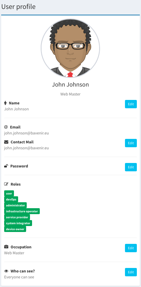
Relationships
The user is linked to other entities as previously mentioned.
| Relation | Description |
|---|---|
| Items | All the devices and services managed by the user |
| Contracts | Agreements to share data where the user participates |
| Notifications | Some actions trigger notifications that are sent to a single user |
| Audits | Keeps track of relevant events for the user (History) |
To visually see all these relationships in the UI is very easy, see below how:
- Items, audits and contracts: Directly in the user profile.
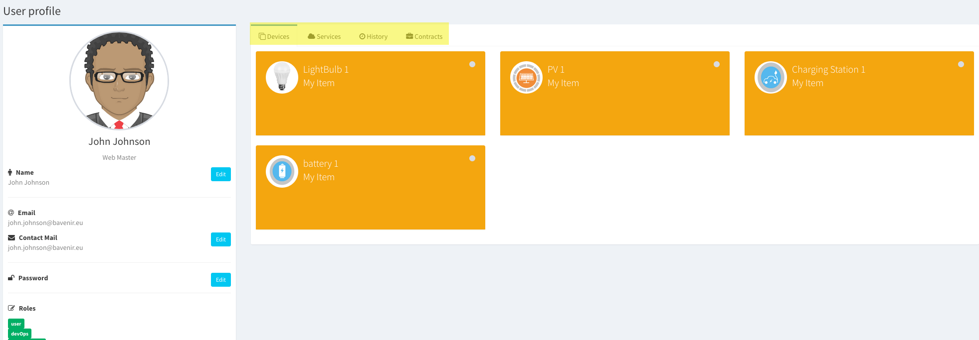
- Notifications: The bell on the top menu shows all notifications addressed to the user.

Roles
There are 6 user roles in the platform:
- User: All users have this role by default
- Administrator: The user that registers an organisation gets this role by default. It can be also granted to other users afterwards. It is necessary to be administrator in order to:
- Modify organisation properties
- Remove and organisation
- Update users roles
- Device owner: A user with this role can enable devices. When enabling a device, the user becomes its responsible platform-wise and it can manage its properties and share its data.
- Service provider: A user with this role can enable services. When enabling a service, the user becomes its responsible platform-wise and it can manage its properties and share its data.
- System integrator: A user that can manage the gateways (agents/adapters) of the platform. Can create, update and remove gateways.
- Infrastructure operator: A user that can initiate contracts. In other words the responsible to choose which service can adequate to some of the devices of its organisation and request it.
The infrastructure operator can be the owner of devices or not (having the role of device owner). In case the devices chosen to be part of a contract do not belong to the infrastructure operator, the actual owners will be asked for permission. The contract will be completed only with those devices whose owners agreed. Additionally there is a role granted by the platform administrator: * superUser: This role is reserved for developers interested in using the API. With this role, it is possible to use a faster registration method.
Organisation management
Besides updating properties there are some other aspects of an organisation that can be managed:
Organisations view
It is one of the tabs in the sidebar menu. It allows to see which organisations exist in the platform and to filter them by friends and not friends.

Friendships
Any user can request to establish a friendship between its organisation and any other. There are 5 possible actions during the partnership process. All of them can be performed from the profile of the potential friend.
- Request partnership
You are initiating the partnership process

- Manage partnership
You receive a partnership request. You can see if you have requests in the notifications area.

Also possible to manage the request from the notifications.

- Cancel partnership
You decide to stop a partnership. The other party will receive a notification.

- Cancel partnership request
You decide to stop a partnership request.

Remove organisation
Users with the administrator role can proceed to remove an organisation from the organisation profile.

User management
An administrator has certain control over its organisation users. As of now, an administrator can remove or change the roles of a user.
Note
Important notes regarding change of roles and user removal: The rules below apply both the case that we want to remove a user or just change a role.
There must be in all moments at least one organisation administrator.
There are some roles that cannot be removed if the user is still bound to some of its responsibilities, i.e:
- A device owner cannot be removed until the user does not have any devices under its responsibility. The devices can be either deleted, disabled or moved to another user.
- A service provider cannot be removed until the user does not have any services under its responsibility. The services can be either deleted, disabled or moved to another user.
- A infrastructure operator cannot be removed until all contracts it is responsible for are either moved to other infrastructure operator or cancelled.
Remove user
It is possible to remove users from the organisation profile, under the tab role management.

Change roles
As mentioned, only administrators can add/remove roles. Otherwise the process is simple and it is located under the organisation profile.


Note
In order for the changes to take effect, the user that had its roles changed might need to log in again.
Infrastructure Management
This section is focused on the infrastructure level. The properties and main features of the infrastructure entities will be explained in the following subsections.
Access Points
This section is about the Access Points, which are the virtual representation of an infrastructure. In a real scenario, an access point represents 2 or 3 components:
- Gateway: Software that is used to communicate with the platform’s communication server and the P2P network. See all information regarding the VICINITY Open Gateway HERE
- Agent: [OPTIONAL] It is used to register the smart components of an infrastructure into the platform. It implements logic to handle the process of registering, updating and removing items from/to the platform. It needs to have the infrastructure components described in a common format. See all information regarding the VICINITY agent HERE
- Adapter: It is the specific software that translates the infrastructure conventions, definitions or API endpoints into the common format. It is mapping all the properties and capabilities of each smart component so the platform can understand what it is. It could implement some of the agent functionalities depending on the needs.
To be able to manage the access points in the platform, a user needs to have the system integrator role. Having this role opens the access point view in the sidebar,
and from this view it is possible to manage all the access points. The image below is going to be referenced in the following sub-sections to describe all its details.

Example figure
Properties
As we can see in the example figure there are 3 main properties.
| Property | Description | Update |
|---|---|---|
| Name | Friendly name | YES |
| AGID* | External ID | NO |
| Type | Indicates to which project belongs the infrastructure | YES |
Note
This is an important field because when initialising the agent/adapter, this ID will be used in the authentication credentials together with the password. The password will be introduced by the system integrator when creating the gateway entity and will not be stored by the web application.
Relationships
The access point belongs to an organisation and at the same time can have several items (devices and services).
| Relation | Description |
|---|---|
| Items | All the smart components and services |
In the example picture it is possible to see the count of items for each infrastructure, in addition, each item has in the profile the name and AGID of its agent/adapter. For system integrators using the Open Gateway API there are calls that return all items registered under the agent/adapter among other interesting options.
Manage
Here we will focus on the highlighted area of the example picture. Those are the actions that can be done over the infrastructure.
- In the first place there is creating a new access point. The process is simple just follow these steps:
- Add a name
- Select a type
- Give a password
- Submit the form

- In the second place, there is a view/modify option. When clicking a new view opens with the access point detail:

If we click over modify the view changes and it is possible to update the name and password of the access point.

- At last, it is possible to remove a access point from the platform. This means that the platform will forget your infrastructure.
Items
This section describes the item entity. In a real infrastructure, an item can be a smart device or a value-added service.
All the items need an adapter/agent and a gateway to be integrated in the platform. Once registered, users with service provider or device owner roles will be responsible for the services and devices respectively.
Properties
In the table is possible to see the most relevant properties, for those which are possible to update there will be a separate sub-section in the last section of this page (“Manage”).
| Property | Description | Update |
|---|---|---|
| Name | Friendly name | NO |
| OID | External ID | NO |
| Type | Indicates if it is a service or device | NO |
| Visibility | Private, for friends, public | YES |
| Info* | Thing description of the item | YES |
| Avatar** | Item logo | YES |
| Status | Enabled/Disabled | YES |
* It can only be updated with the adapter/agent ** Can be updated clicking over it and selecting a new picture from the folder
Note
Info property: Thing description of the item In the item profile, there is a tab call “Description” that shows a series of collapsible tiles containing all the properties that define the Thing Description of the item. We can find there all the available properties and actions for the given item. This properties, actions and events are the same that can be requested using the consumption endpoints of the Open Gateway API

Relationships
The items belong to a gateway and to a user. It can have contracts and audits.
| Relation | Description |
|---|---|
| Contracts | Agreement to share device data |
| Audits | Most relevant events of the item (History) |
Manage
See the platform items In the sidebar menu, there are two tabs for the items: Devices (Orange widget) and services (Yellow widget). These views show your items, public items and items of your friends that are flagged as “visible for friends”. There are as well filtering options.

Each widget contains certain information about the item. We can see in the device widget a yellow-highlighted area with the item name and the organisation that owns the item. Right below there is a green-highligted are showing the status and visibility of the item. There is also an avatar on the top left corner and the logo type of adapter that has integrated the item on the right bottom corner. Finally, at the bottom there is a line with the owner of the item and a link to the profile.

Device widget
In the service widget there is also a green action button in the case that the service is possible to request. Pressing +Request Service would initiate the contract process.

Service widget
Status & visibility
An item can go through several status and visibility levels, see the table below to understand some of the possible actions and effects in the item lifecycle.
| Action | Visibility | Status | hasGateway | hasOwner |
|---|---|---|---|---|
| Agent registers item in platform | Private | Disabled | YES | NO |
| User enables item | Private | Enabled | YES | YES |
| User makes item visible for friends | Visible for friends | Enabled | YES | YES |
| User makes item public | Public | Enabled | YES | YES |
| User disables item | Private | Disabled | YES | NO |
| User deletes item | N/A | Deleted | NO | NO |
Note
IMPORTANT: In order to assign a visibility level the device must be enabled. As well, it is important to remember that the visibility level of a device must remain lower than the visibility of its user owner.
Now we will see the all possible status and visibility levels and how to change them from the item profile.
- Status There are three possible status for an item:
- Disabled: When an item has just been registered, it appears as disabled in the platform. An item can be disabled by its owner anytime. Being disabled means that the item is private and is not visible in the P2P network. Furthermore a disabled item does not have owner assigned in the platform.
- Enabled: When a user claims an item, this turns to the enabled status. Now it is possible to change the visibility level and use it in contracts. It is possible to see the following changes in the “Disabled vs Enabled” picture.
- New section with visibility settings
- User owner of the item added
- Button to change user enabled
- New section with a button to remove the device

Disabled vs Enabled
- Deleted: The owner of the item can decide to remove it from the platform. This will remove the item from all existing contracts and it will make it no longer visible in the platform. This action can also be triggered using the agent.

- Visibility
There are also three visibility levels: * Private: Only my organisation can see the item. * Visible for friends: Other organisations that are partners with mine can see the item and request its data making use of a contract. * Public: All organisations can see the item and request its data making use of a contract.
To change the visibility go to the item profile and use the option highlighted. Remember to enable the device and set the visibility of your user adequately. See the process below:

Move an item
It is possible to change the owner or gateway of an item without interfering existing contracts or doing any additional changes. For that it is necessary to be the current owner of the device or an organisation administrator. Nevertheless, there are some conditions that have to be met:
- Case of changing a gateway: New gateway needs to have the same type. I.e: Vicinity agent to Vicinity agent.
- Case of changing owner: New user need to have device owner or service provider role (Depending on the item you are moving). The privacy level of the item you are moving will be reduced if the new user has lower visibility, be aware that this can cause that your device will be removed from some contracts. *Check the visibility of the new user
to avoid issues.*
Moving an item can be specially useful in the situation of a leaving employee or change of responsibilities within an organisation. The status of the items under the responsibility of this person will remain unchanged, but we can have a different person in charge.
To move an item go to the item profile and select one of the options in the move item menu. When you click over change owner or change gateway, you will see a dropdown menu where you can select the desired option and finish the process by clicking save.
Note
Note that if the device is disabled you will only be able to change the gateway because there is no item owner at the moment.

Contracts
This section covers one of the last additions to the platform, the contracts. Through contracts is how devices and services of different organisations can share data and interact.
Currently there is only one contract type “Service Request”. In this type of contract, services and devices from organisation_one can request to use a service from organisation_two. This service will be monitoring (or monitoring and controlling) those items that were added to the contract by organisation_one.
In order to create a contract we need to follow these steps:
- A user with role Infrastructure Operator selects a service (public or from a partner organisation)
- Then the Infrastructure Operator needs to choose the contract settings:
- Select items (with fitting visibility) from his organisation. Can be from different users.
- Choose if we want to give write rights to the service or not.
- Approve the terms and conditions.
- A notification will be sent to the service owner.
- Once the service provider approves the contract, the service can start sharing data with the items belonging to the Infrastructure Operator, if he had any. All other items that belong to different users will not be part of the contract until their owners give consent.
- Therefore, the next step is to send a notification to all users so they can approve or reject the contract.
- In the end the contract is completed with the Infrastructure Operator, Service Provider and all other users that gave consent to share data.
- Any time a user can withdraw from the contract. In the subsequent points we will define the properties, relations and actions that the contract has got in order to fulfil its purpose.

Note
- Important notes:
- To request a service you need to be IoT operator.
- If the contract includes devices that belong to your organisation, but you are not the owner, then the respective owners will need to agree the contract. Meanwhile, these devices will appear as inactive or disabled, and will not be reachable by the service.
- All users with devices/services in the contract, will see the contract in their respective contracts view.
- The IoT operator and the service provider are considered administrators of the contract. They can cancel the contract anytime unilaterally. If a user that is not admin, presses the button to remove the contract, only itself and its devices will be removed. The contract will remain with the rest of the users.
- The items involved in the contract can be managed individually, but only by their owners.
Properties
In the table is possible to see the most relevant properties, for those which are possible to update there will be a separate sub-section in the last section of this page (“Manage”).
| Property | Description | Update |
|---|---|---|
| CTID | External ID | NO |
| IoT Owner* | Object with relevant info of the infrastructure owner | YES |
| Foreign IoT* | Object with relevant info of the service owner | YES |
| Status | Active or deleted | YES |
| R/W | Monitor or monitor & control | NO |
| T&C | Terms and conditions | YES |
| Type | Right now, only service request | NO |
- (*) IoT Owner and foreign IoT contain:
- Users with items involved in the contract;
- Information about the organisations the users belong to;
- Items in the contract with a flag stating whether they are active or not;
- Flag indicating if the terms and conditions were accepted. Only the IoT Provider and the Service Provider need to approve the T&C on behalf of the rest of users. However, each user can decide if its devices are included in the contract.
Relationships
Each item and user involved in a contract has information of it stored in an array of contracts.
| Property | Description | Update |
|---|---|---|
| CTID | External ID | NO |
| ID | Mongo ID | NO |
| imForeign | If true, user is service provider | NO |
| imAdmin | If true, user is IoT Operator (or Service Provider if ImForeign = TRUE) | NO |
| approved | Indicates whether the user has agreed T&C | YES |
| inactive | Array with user inactive devices | YES |
| readWrite | Contract with monitor or control capabilities | NO |
| contractingUser | ID of the administrator of the other side of the contract | NO |
| contractingParty | ID of the organisation of the other side of the contract | NO |
Main views
Request contract
To access this view a user with IoT Operator role needs to click on the “request service” button of any eligible service.
- Read the description of the service you are requesting.
- Select the devices/services you would like to include in the contract.
- Grant control or control&monitoring permissions to the service over your infrastructure.
- Read and accept the terms and conditions.

All contracts view
To access this view users with “device owner”, “service provider” or “IoT Operator” roles, just need to click on the sidebar the contracts link. 1. See if your organisation is providing (red flag) or using the service (green flag). 2. See some important information: Service name, service provider name, owner of the infrastructure, number of items in the infrastructure, status of the contract, and type and permissions. 3. Actions: Approve, see details and cancel contract.

Contract detail
To access this view users with “device owner”, “service provider” or “IoT Operator” roles, just need to click on the eye icon that you will find in each contract instance of the “all contracts view”. 1. Information of the service provider and service used. 2. Legal description of the contract. 3. Items info:
- Name, OID, type of item, owner, status and actions.
- Actions are affecting status of the items in the contract. It is possible to enable, disable and remove item from the contract.
4. Contract action buttons: * Transfer contract, accept contract, remove contract and close details.

Manage
Create a contract
- Select a service and click “Request service”. Do it from the services view or from a service profile.
- The “request service view” opens, there you can see all the information about the service you are requesting and select the items that you would like to share with it. Also it is possible to grant read or read/write permissions to the service over your devices.
- Once you agree the terms and conditions, it is possible to submit the contract request.
- Now the contract appears in the “all contracts view” (sidebar menu). The contract will be active once the service provider accepts the request.
- All parties should receive notifications with the status of the contract.

Accept, see or remove a contract
Within the “all contracts view” you have several actions for each contract.
- See details: Represented by an eye. Opens the “contract detail view”.
- Accept a contract: Green check sign.
- If you are an administrator: Accepts contract.
- If you are a normal user: Enables your devices in the contract.
- Remove contract: Red cross.
- If you are an administrator: Removes contract.
- If you are a normal user: Removes you and your items from the contract.

Transfer a contract It is possible to transfer the responsibility of being the administrator of a contract. To do so click in the exchange button in the “contract detail view” and select a suitable recipient for the responsibility. That would be some user with the IoT Operator role.

Enable, disable and remove devices within a contract Each item can be managed individually by its owner. To do so, navigate to the “contract detail view” and at the bottom you will see all the items. Only those which are your will have actions available.
Enabling (green check) and disabling (pause sign) keep the item in the contract. A disabled/inactive device cannot be reached by the service.
Removing (red cross) a device, deletes all links of the device with the contract. After removing the device it is not possible to enable it back.

Update items in the contract
A system integrator may update devices or services in the infrastructure, and these items might be involved in some contracts. This could be an issue, since the updated item might have new properties or actions that were not included in the terms of conditions of previously existing contracts. To cope with this problem, the update process modifies the contracts in the following manner:
- When updating a device:
- The device is put to disabled mode in all contracts.
- Contracts flag the device as inactive.
- The owner of the device is notified and then it is possible to revise the T&C and accept or reject them.
- If the device owner accepts the conditions the device will be added to the contract again, if not, will be permanently removed.
- When updating a service:
- The contract is moved to the state when all parties need to approve the T&C, it suffers a reset.
- The items included in the contract cannot communicate anymore, until their owners approve the new T&C. 3. All the users involved in the contract are notified, and once they approve the T&C, the contract is re-established.
Platform Evaluation
This section contains tools to evaluate the complexity of the platform.
Tests
There have been set up some tests to check some of the functionalities of the platform. There is a special focus on the API. We will see in this section how to run the tests.
Note
This functionality is available for the server only. (Navigate to the server root folder to execute the scripts that you will find below)
- Set up a test db
(In the section Platform deployment, there is more info regarding how to setup Mongo, create users or add authorisation to access databases)
- Create a clean mongo database. We will assume the name “nmapitest”.
- Authorize one user to make use of this database. We will assume user and password to be “test”.
- Insert a first user in “users” and organisation in “useraccounts” into the db “nmapitest”:
db.useraccounts.insert({ "avatar" : "", "location" : "SomeCountry", "cid" : "admin-test", "name" : "adminCorp", "businessId" : "1234-5678", "hasNotifications" : [], "knowsRequestsTo" : [], "knowsRequestsFrom" : [], "knows" : [], "status" : "active", "skinColor" : "blue" })db.users.insert({ "email" : "admin@admin.com", "occupation" : "Web Master", "avatar" : "", "name" : "admin", "authentication" : { "hash" : "$2a$10$EFuFLZGxhfgScAnR/.aj9Osnbw/4sTmHcW2guFesyIChSr8w/bSHC", "principalRoles" : [ "user", "administrator", "infrastructure operator", "service provider", "device owner", "system integrator", "devOps", "superUser" ] }, "accessLevel" : 2.0, "status" : "active" })
Then update them as follows. Remember to replace the id with ObjectId(” ID OF THE NEW ORGANISATION OR USER “) that you obtained in the previous step:
db.useraccounts.update( {cid: "admin-test"}, {$set: { "accountOf" : [ { "id" : < OBTAINED WHEN INSERTING >, "extid" : "admin@admin.com" } ]} })db.useraccounts.update( {email : "admin@admin.com"}, {$set: { "cid" : { "id" : < OBTAINED WHEN INSERTING >, "extid" : "admin-test" } } })
- Once the db is ready replace in the package JSON the script test with the following:
"test": "env=test VCNT_MNGR_DB=mongodb://test:test@ < YOUR IP or LOCALHOST > :27017/nmapitest nyc mocha './test/**/*.spec.js'"
- Finally, to run the test execute:
npm run test
Complexity
Measures the complexity of the code. It is based on the cyclomatic complexity of the functions among other measurements.
Note
This functionality is available for the server only. (Navigate to the server root folder to execute the scripts that you will find below)
Run at module level:
npm run complexity
Run at function level. Highlights the most complex functions per module:
npm run complexity-detail
F.A.Q
Frequent asked questions section
Find information about how to resolve common issues or use certain functionalities. This section can be updated with platform users feedback.
How can I recover my password?
It is not possible to send you your old password for security reasons, however we can help you reset your password following a series of simple steps:
- Navigate to the login page and click “recover password”

- Introduce your mail address and send the request for new password
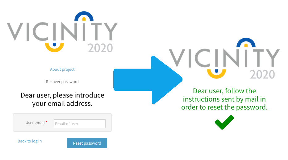
- Go to your mail and follow the link for changing your password
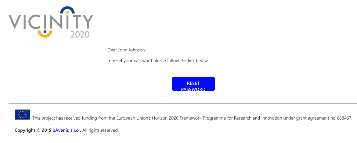
- Change the password and you are all set
How can I change my password?
It is possible to change your password using the user interface. To do so, follow these steps:
- Navigate to the user profile

- Click on edit password

- Change and submit your new password.

Can I keep a session open in my browser?
If you want to keep open your session and avoid typing your password every time, we can do that for you. Just check the box highlighted in the picture. Use this feature responsibly and preferably only in your personal computer to prevent unauthorised access to your account!

How can I use the platform REST API?
The platform offers a way to programatically use some of its functionalities. Thus developers can build their own value added services or user interfaces using the platform backend.
Everyone with a valid organisation registered can use the API and all the documentation is available following the link below:
VICINITY Vocabulary
- VICINITY Cloud
- The VICINITY Cloud enables IoT infrastructure operators and Service providers to configure a virtual neighbourhood of connected devices and value-added services including the setup of sharing access rules between them through the user-friendly interface of VICINITY Neighbourhood Manager accessible through http://vicinity.bavenir.eu.
- VICINITY Node
- A VICINITY Node is the set of software components which maintains the user data exchange between peers in the VICINITY P2P network based on configuration of the virtual neighbourhood and sharing rules received from VICINITY Communication Server. VICINITY Node is collection of software components (VICINITY Gateway API, VICINITY Agent and VICINITY Adapter) enables your IoT infrastructure or services communicates with other VICINITY enabled devices and services.
- VICINITY Adapter
The VICINITY Adapter is a component provided by IoT infrastructure owner/ vendor or respective system integrator. The VICINITY Adapter provides translates the VICINITY “world” into the IoT infrastructure specific environment. The core responsibilities of the Adapter are:
- to provide the description of each IoT objects (devices, services) of infrastructure in common VICINITY format, which enables VICINITY to create internal models of used IoT objects in uniform way;
- to provide access to properties, actions and events of devices and services provided by infrastructure.
- VICINITY Gateway API
- The VICINITY Gateway API provides services to access VICINITY Peer-to-peer network. It is primary interface towards VICINITY Platform.
- VICINITY Agent
- The VICINITY Agent is the wrapper for the VICINITY Adapter. The VICINITY Agent provides the full VICINITY specific functionality, as managing communication via P2P network, semantic discovery of IoT objects (devices and services), semantic search of IoT objects, communication with IoT objects within the infrastructure, where each VICINITY specific interaction with IoT objects is translated in the VICINITY Adapter calls. In general, VICINITY Agent simplifies the communication with VICINITY Gateway API especially with IoT objects (device and services) registration and update.
- Agent ID (agid)
- The Agent ID is UUID (VICINITY Platform unique key) which represents adapter in VICINITY peer-to-peer network. The agent Id is generated during registration of the access point in VICINITY Neighbourhood manager (https://github.com/vicinityh2020/vicinity-neighbourhood-manager/wiki/Access-points). The agent ID is used during login of the VICINITY Adapter into the peer-to-peer network and during registration of IoT objects.
- Object ID (oid)
- The Object ID is UUID (VICINITY Platform unique key) which represents any device and service registered in VICINITY. This ID is used to access devices and services properties, actions and events. The ID is generated during device and service registration via VICINITY Gateway API.
- Property ID (pid)
- The Property ID is UUID (IoT object unique key) which represents any property provided by the device or service.
- Action ID (aid)
- The Action ID is UUID (IoT object unique key) which represents any action provided by the device or service.
- Event ID (eid)
- The Event ID is UUID (IoT object unique key) which represents any event provided by the device or service.
- IoT Object
- The IoT object is any device or service registered in VICINITY Platform. The IoT object is referenced by uniq oid generated during its registration. The IoT object is represented by Thing description. In terms of devices, the IoT object represents a virtual device.
- Virtual device
The virtual device represents set of device(s) capabilities (such as current temperature, on/off switch, etc.). The set of device(s) capabilities can be represented in the real world as follows: * 1-on-1: virtual device have the same set of capabilities as physical one represented by the virtual one; * subsetting: virtual device have the subset of physical device capabilities, Note that capabilities which are not provided by virtual device will not be accessed through the VICINITY; * union: virtual device represents the multiple physical devices in one virtual device.
Attention
Currently VICINITY support any access restrictions on the level of virtual device. Enabling access to union virtual device results in access to all related physical devices by design. Enabling access to 1-on-1 virtual device results in access to all capabilities of physical device. Hence it is advised to follow subsetting virtual device approach.
The virtual device is represented by one Thing description.
- Thing description (TD)
- The thing description is JSON object providing identification of IoT object and description of each IoT object capabilities (properties, actions and events) (https://github.com/vicinityh2020/vicinity-agent/blob/master/docs/TD.md ).